background image

3. TECHNICAL BRIEF

- 60 -

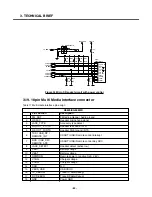
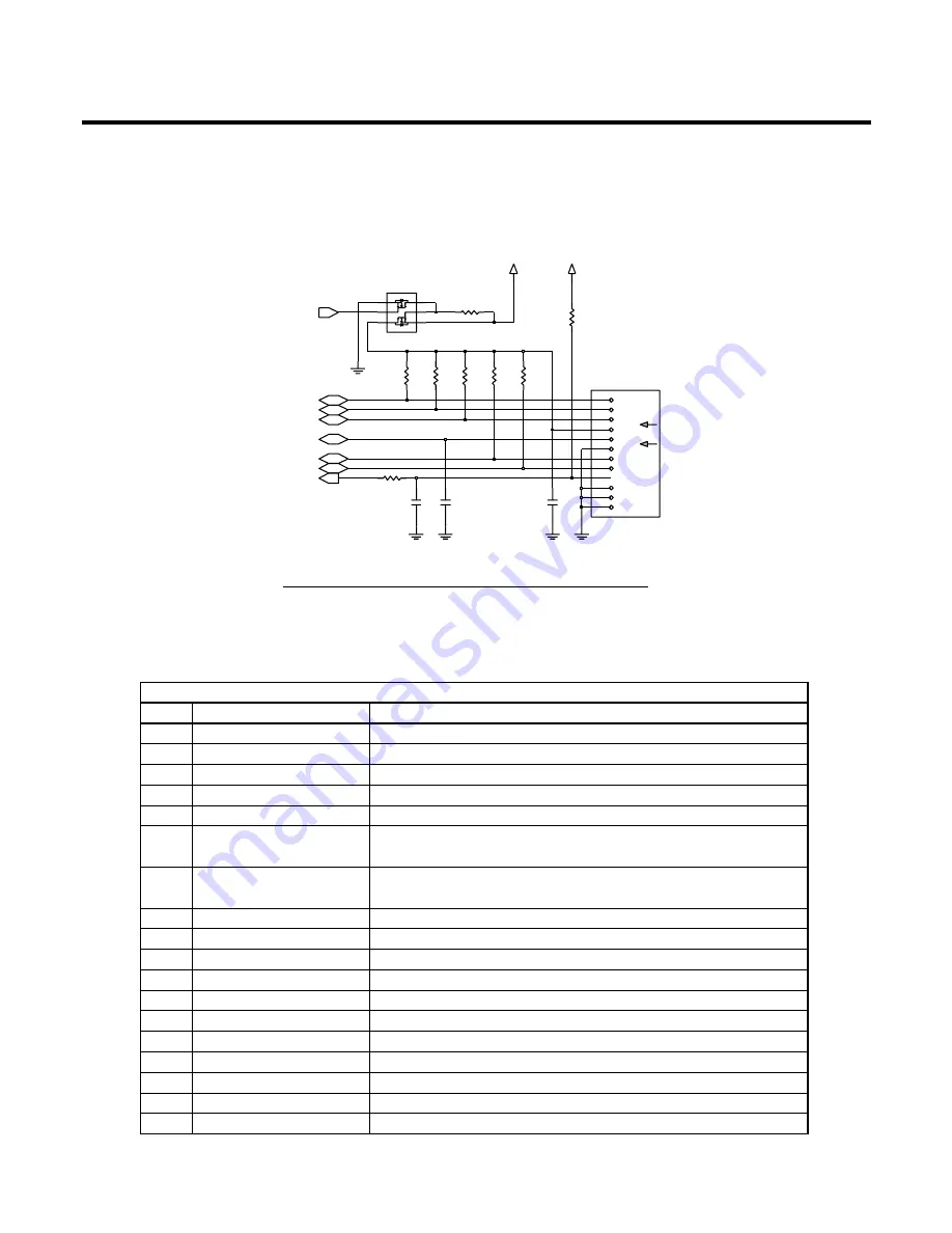
3.19. 18pin Multi Media Interface connector

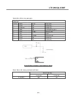
Table 11 Multi media interface pin assign

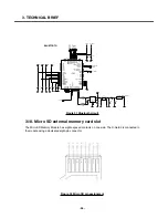
1000p

C156

2V72_IO

100K

R132

R130

100K

100K

R133

22p

C142

R183

47

R134

100K

R136

100K

C143

1uF

2V85_CARD

R137

100K

100K

R135

VSS

CD_DAT3_CS

CLK_SCLK

CMD_DI

COMMON

DAT0_DO

DAT1_RSV

DAT2_RSV

DETECT

DUMMY1

DUMMY2

VDD

S100
SCHA1B0102

5

S1

1

4

S2

Q1

NTJD4105CT1G

6

D1

D2

3

2 G1

G2

TF_CLK

TF_DAT0
TF_DAT1

TF_PWR_EN

TF_DETECT

TF_DAT2
TF_DAT3

TF_CMD

Figure 34 Micro SD socket circuit with power control

KE820/KG99 MMI

Pin Function 

Description

1

FM_ANT

FM radio antenna / Audio ground

2

HS_MIC

Headset microphone signal

3

JACK_TYPE

Accessory type detect

4

HS_OUT_L / CTS

Headset left sound / CTS

5

HS_OUT_R / RTS

Headset Right sound / RTS

6

TXD / USB_DP /

USART / USB/ Remote control interrupt

REMOTE_INT

7

RXD / USB_DM /

USART / USB/ Remote control Key ADC

REMOTE_ADC

8

JACK_DETECT

Headset detect (active low)

9

VBAT

Battery voltage

10

VBAT

Battery voltage

11

RPWRON 

Remote power on (active high. 2.8V)

12

VCHG Charger 

voltage

13

VCHG

Charger voltage

14

DSR

N.C.

15

VBUS_USB

USB VBUS

16

TX_DEBUG

Trace TX data(Debug)

17

RX_DEBUG

Trace RX data(Debug)

18

GND

Power GND

Summary of Contents for KE820

Page 1: ...Service Manual Model KE820 Service Manual KE820 Date August 2006 Issue 1 0 ...

Page 2: ...reserves the right without notice to make changes to equipment design as advances in engineering and manufacturing methods warrant This manual provides the information necessary to install program operate and maintain the KE820 KG99 REVISED HISTORY Editor Date Issue Contents of Changes S W Version T K CHOI 2006 03 29 0 1 T K CHOI 2006 07 06 0 2 ...

Page 3: ... 4 ...

Page 4: ...ceiver part 63 3 22 Transmitter part 64 3 23 RF synthesizer 66 3 24 VCTCXO 66 3 25 Front End Module control 67 3 26 Power Amplifier Module 67 4 PCB layout 69 4 1 Main Sub PCB component placement 69 5 Trouble shooting 76 5 1 Trouble shooting test setup 76 5 2 Power on Trouble 76 5 3 Charging trouble 80 5 4 LCD display trouble 82 5 5 Camera Trouble 83 5 6 Receiver Speaker trouble 86 5 7 Microphone t...

Page 5: ... 6 ...

Page 6: ...sponsible for any charges that result from such unauthorized use B Incidence of Harm If a telephone company determines that the equipment provided to customer is faulty and possibly causing harm or interruption in service to the telephone network it should disconnect telephone service until repair can be done A telephone company may temporarily disconnect service as long as repair is not done C Ch...

Page 7: ...quipment medical equipment etc Interference from unsuppressed engines or electric motors may cause problems H Electrostatic Sensitive Devices ATTENTION Boards which contains Electrostatic Sensitive Device ESD are indicated by the sign Following information is ESD handling Service personnel should ground themselves by using a wrist strap when exchange system boards When repairs are made to a system...

Page 8: ...ive to 1 milli watt DSP Digital Signal Processing EEPROM Electrical Erasable Programmable Read Only Memory EGPRS Enhanced General Packet Radio Service EL Electroluminescence ESD Electrostatic Discharge FPCB Flexible Printed Circuit Board GMSK Gaussian Minimum Shift Keying GPIB General Purpose Interface Bus GPRS General Packet Radio Service GSM Global System for Mobile Communications IPUI Internati...

Page 9: ...Rating RMS Root Mean Square RTC Real Time Clock SAW Surface Acoustic Wave SIM Subscriber Identity Module SLR Sending Loudness Rating SRAM Static Random Access Memory STMR Side Tone Masking Rating TA Travel Adapter TDD Time Division Duplex TDMA Time Division Multiple Access UART Universal Asynchronous Receiver Transmitter VCO Voltage Controlled Oscillator VCTCXO Voltage Control Temperature Compensa...

Page 10: ...PL 5 DCS PCS 30dBm PL 0 GPRS compatibility Class 10 SIM card type 3V Small Display 220 X 176 pixels 2 inch wide 265K color TFT Soft icons Key Pad Status Indicator 0 9 Navigation Key Send End 2 Function Key END PWR MP3 AF Camera double action Volume Up Volume Down ANT Built in antenna EAR Phone Jack 18pin multi port Headset jack with Remote controller PC Synchronization Yes Speech coding HR EFR FR ...

Page 11: ...degrees 3 Frequency Error 0 1ppm GSM900 EGSM Level Power Toler Level Power Toler 5 33 dBm 2dB 13 17 dBm 3dB 6 31 dBm 3dB 14 15 dBm 3dB 7 29 dBm 3dB 15 13 dBm 3dB 8 27 dBm 3dB 16 11 dBm 5dB 9 25 dBm 3dB 17 9 dBm 5dB 10 23 dBm 3dB 18 7 dBm 5dB 11 21 dBm 3dB 19 5 dBm 5dB 4 Power Level 12 19 dBm 3dB DCS1800 PCS1900 Level Power Toler Level Power Toler 0 30 dBm 2dB 8 14 dBm 3dB 1 28 dBm 3dB 9 12 dBm 4dB...

Page 12: ...60 1 800 3 000 63 3 000 6 000 65 5 Output RF Spectrum 6 000 71 due to modulation DCS1800 PCS1900 Offset from Carrier kHz Max dBc 100 0 5 200 30 250 33 400 60 600 1 200 60 1 200 1 800 60 1 800 3 000 65 3 000 6 000 65 6 000 73 GSM900 EGSM Offset from Carrier kHz Max dBm Output RF Spectrum 400 19 6 due to switching transient 600 21 1 200 21 1 800 24 ...

Page 13: ...ER Class II 2 439 102dBm DCS1800 PCS1900 BER Class II 2 439 100dBm 9 Rx Level Report accuracy 3 dB 10 SLR 8 3 dB Frequency Hz Max dB Min dB 100 12 200 0 300 0 12 11 Sending Response 1 000 0 6 2 000 4 6 3 000 4 6 3 400 4 9 4 000 0 12 RLR 2 3 dB Frequency Hz Max dB Min dB 100 12 200 0 300 2 7 500 5 13 Receiving Response 1 000 0 5 3 000 2 5 3 400 2 10 4 000 2 Mean that Adopt a straight line in betwee...

Page 14: ...y Capacity 750mA 180 min EGSM Lvl12 Battery Capacity 750 mA 320min Under conditions at least 300 hours 1 Brand new and full 750mAh battery 22 Standby Time 2 Full charge no receive send and keep GSM in idle mode 3 Broadcast set off 4 Signal strength display set at 3 level above 5 Backlight of phone set off At least 65 dB under below conditions 23 Ringer Volume 1 Ringer set as ringer 2 Test distance...

Page 15: ... 85V 2 3 75V 3 69V 1 3 69V 3 62V 0 3 62V 27 Low Voltage Warning 3 62V 0 05V Call 3 50V 0 05V Standby 28 Forced shut down Voltage 3 35 0 05 V Li ion Battery 29 Battery Type Standard Voltage 3 7 V Battery full charge voltage 4 2 V Capacity 750mAh Switching mode charger 30 Travel Charger Input 100 240 V 50 60Hz Out put 4 8 0 9A ...

Page 16: ... 5dB 9 25dBm 3dB 17 9dBm 5dB 10 23dBm 3dB 18 7dBm 5dB 11 21dBm 3dB 19 5dBm 5dB 5 Power Level 12 19dBm 3dB DCS1800 PCS1900 Level Power Toler Level Power Toler 0 26dBm 3dB 8 14 dBm 3dB 1 26dBm 3dB 9 12 dBm 4dB 2 26dBm 3dB 10 10 dBm 4dB 3 24 dBm 3dB 11 8 dBm 4dB 4 22 dBm 3dB 12 6 dBm 4dB 5 20 dBm 3dB 13 4 dBm 4dB 6 18 dBm 3dB 14 2 dBm 5dB 7 16 dBm 3dB 15 0 dBm 5dB 6 Output RF Spectrum GSM900 EGSM due...

Page 17: ...arrier kHz Max dBc 100 0 5 200 30 250 33 400 54 600 1 200 60 1 200 1 800 60 1 800 3 000 63 3 000 6 000 65 6 000 71 7 Output RF Spectrum GSM900 EGSM due to switching transient Offset from carrier kHz Max dBm 400 23 600 26 1 200 27 1 800 30 DCS1800 PCS1900 Offset from carrier kHz Max dBm 400 23 600 26 1 200 27 1 800 30 ...

Page 18: ...AL BRIEF 19 Baseband circuit 3 1 KE820 KG99 Component Block diagram KE820 KG99 is composed with 3 different PCB part such as main PCB sub PCB and FPCB 3 TECHNICAL BRIEF Figure 1 KE820 KG99 Hardware architecture ...

Page 19: ...3 TECHNICAL BRIEF 20 The functional component arrangement is mentioned below diagram Figure 2 KE820 KG99 Functional block diagram ...

Page 20: ...such as camera software MIDI MP3 sound It is designed as a single chip solution integrating the digital and mixed signal portions of the base band in 0 13um 1 5V technology The chip will fully support the FR EFR HR and AMR NB vocoding S GOLD2TM support multi slot operation modes HSCSD up to class 10 GPRS for high speed data application up to class 12 and EGPRS up to class 12 without additional ext...

Page 21: ...onnected by powerful buses Multi layer AHB for connecting the ARM and the other master capable building blocks with the internal and external memories and with the peripheral buses Clock system The clock system allows widely independent selection of frequencies for the essential parts of the S GOLD2 Thus power consumption and performance can be optimized for each application Functional Hardware bl...

Page 22: ...face e g connection to S M power A fast display interface supporting serial and parallel interconnection An ITU R BT 656 compatible Camera interface Programmable clock output for a camera An multimedia Secure Digital Card Interface MMCI SD SDIO capable 3 2 3 External Devices connected to memory interface Table 1 Memory interface 3 2 4 RF Interface T_OUT S Gold2 uses this interface to control RF IC...

Page 23: ...0 USART1 Resource Name Remark USART0_TXD TXD_0 Transmit Data USART0_RXD RXD_0 Receive Data USART0_CTS CTS_0 Clear To Send USART0_RTS RTS_0 Request To Send DSR N C USART_1 USART2 USART1_TXD TX_DEBUG Trace data tx USART1_RXD RX_DEBUG Trace data rx USART1_CTS N C N C USART1_RTS N C N C ADC channel Resource Interconnection Description M0 BATT_TEMP Battery temperature measure M1 RF_TEMP RF block temper...

Page 24: ...x KP_IN3 KP_IN3 Refer to Key Matrix KP_IN4 KP_IN4 Refer to Key Matrix KP_IN5 KP_IN5 Refer to Key Matrix KP_OUT5 KP_OUT5 Refer to Key Matrix KP_OUT0 KP_OUT0 Refer to Key Matrix KP_OUT1 KP_OUT1 Refer to Key Matrix KP_OUT2 KP_OUT2 Refer to Key Matrix KP_OUT3 KP_OUT3 Refer to Key Matrix USART_0 USART0_RXD RXD_0 UARTO RS232 Data USART0_TXD TXD_0 UARTO RS232 Data USART0_RTS_N CTS_0 UARTO RS232 RTS USART...

Page 25: ...ra pixel clock CIF_HSYNC CIF_HS Camera H sync CIF_VSYNC CIF_VS Camera V sync CLKOUT CIF_MCLK Camera main clock CIF_PD CIF_PD Camera power down active high CIF_RESET CIF_RESET Camera reset LCD IF DIF_D0 DIF_D 0 LCD data 0 DIF_D1 DIF_D 1 LCD data 1 DIF_D2 DIF_D 2 LCD data 2 DIF_D3 DIF_D 3 LCD data 3 DIF_D4 DIF_D 4 LCD data 4 DIF_D5 DIF_D 5 LCD data 5 DIF_D6 DIF_D 6 LCD data 6 DIF_D7 DIF_D 7 LCD data...

Page 26: ...ARD CLOCK CC_RST SIM_RST SIM CARD RESET I2S I2S2_CLK0 Not Use GPIO_102 _WP Not Connected I2S2_RX Not Use I2S2_TX Not Use I2S2_WA0 Not Use I2S2_WA1 Not Use EXTERNAL MEMORY MMCI_CMD TF_CMD For T Flash MMCI_DAT 0 TF_DAT0 MMCI_CLK TF_CLK BT I F USIF_TXD_MTSR USIF_TXD For Bluetooth USIF_RXD_MRST USIF_RXD GPIO_109 _USB_EOC USB End of charging detect High EOC Low charging GPIO_110 RPWRON Remote power on ...

Page 27: ...ICP1 MIC1_P MICN2 MIC2_N For Headset Mic MICP2 MIC2_P VMICP VMICP For Mic VMICN VMICN ADC M_0 BAT_TEMP Battery temperature detect M_1 RF_TEMP RF Power amp reference temperature detect M_2 JACK_TYPE For 18Pin Cable Type Detect M_7 HW revision indication M_8 Battery voltage measurement M_9 I_MONITOR Current consumption measurement M_10 REMOTE_ADC For Remote Control Headset Key detect with REMOTE_INT...

Page 28: ...ACEPKT 5 TRACEPKT 6 TRACEPKT 6 TRACEPKT 7 TRACEPKT 7 Data bus EBU_AD 0 D 0 Data bus 0 EBU_AD 1 D 1 Data bus 1 EBU_AD 2 D 2 Data bus 2 EBU_AD 3 D 3 Data bus 3 EBU_AD 4 D 4 Data bus 4 EBU_AD 5 D 5 Data bus 5 EBU_AD 6 D 6 Data bus 6 EBU_AD 7 D 7 Data bus 7 EBU_AD 8 D 8 Data bus 8 EBU_AD 9 D 9 Data bus 9 EBU_AD 10 D 10 Data bus 10 EBU_AD 11 D 11 Data bus 11 EBU_AD 12 D 12 Data bus 12 EBU_AD 13 D 13 Da...

Page 29: ... A 11 Address bus 11 EBU_A 12 A 12 Address bus 12 EBU_A 13 A 13 Address bus 13 EBU_A 14 A 14 Address bus 14 EBU_A 15 A 15 Address bus 15 EBU_A 16 A 16 Address bus 16 EBU_A 17 A 17 Address bus 17 EBU_A 18 A 18 Address bus 18 EBU_A 19 A 19 Address bus 19 EBU_A 20 A 20 Address bus 20 EBU_A 21 A 21 Address bus 21 EBU_A 22 A 22 Address bus 22 EBU_A 23 A 23 Address bus 23 EBU_A 24 A 24 Address bus 24 EB...

Page 30: ...50 KP_OUT 4 Key pad GPIO_51 AU_PWR_EN Audio amp power enable active high CC1CC3IO LCD BACKLIGHT LCD Backlight Control GPIO_53 JACK_DETECT For Headset Detect High unplugged Low plugged GPIO_54 _FM_RESET FM Radio chip reset GPIO_55 AF_PWR_EN Auto focus power enable active high RF_STR0 EN RF Transceiver chip enable GPIO_57 TF_DETECT Micro SD card detect High inserted Low ejected RF_DATA DA RF Transce...

Page 31: ...z RESET_n _RESET Baseband processor reset CC1CC1IO TRIG_OUT For JTAG ETM Interface RTC_OUT RTC_OUT Wake up signal to alarm High wake up Low Power off VCXO_EN VCXO_EN 26MHz clock enable DSP DSPIN0 _BT_RESET Bluetooth chip reset GPIO_62 Not Use GPIO_63 _SIM_EN SIM card power enable ...

Page 32: ... power down concept Low drop out LDO regulators for Flash and mobile RAM memory devices Voltage independent switching of two SIM cards LDO regulators for baseband I O supply LDO regulator for analog mixed signal section of S GOLD Low noise LDO regulators for RF devices Supply for Bluemoon Single Infineon s single chip solution for Bluetooth Audio amplifier 8 Ohms for handsfree operation and ringin...

Page 33: ...C DC converter makes up to 40 reduction of battery current for smart phone functions e g organizer functions games MP3 decoding possible SDBB has high efficiency up to 95 and also a power save mode Memory Interface is directly supported by the SDBB SDBB can also act as main supply voltage for E GOLD or S GOLDlite baseband devices For S GOLD two linear regulators for DSP and Core are cascaded after...

Page 34: ...ce of S GOLD Regulated voltage for S GOLD USB interface including reverse current and over voltage protection Switch to supply USB pull up resistor Mini host pull down resistor functionality Charge pump with internal switching capacitor for USB host VBUS supply voltage SM POWER fully supports LED and Vibra Motor functionality no external components needed driver for backlight LEDs adjustable in st...

Page 35: ...SB 3V1_USB 3 1V 45mA USB I F Figure 5 Power domain block diagram of KE820 KG99 VBAT PM_INT PWRON _RESET SDA SCL PMIC PMB6812 SDBB 850mA LBB1 170mA LBB2 300mA LANA 220mA LINT 135mA LSIM 22mA LSIM2 200mA LMMC 135mA LUSB 45mA LRTC 0 3mA LRFC 120mA LRFC1 250mA LRFC2 10mA LRFC3 150mA I2C BUS INTERFACE CONTROL LED 3 Charge Control Audio amp Memory PF38F5060M0Y0B0 BBP PMB8876 1V8_MEM 1V5_DSP 1V5_CORE 2V6...

Page 36: ...7 VSSAU 8 VSSFB 7 VSSPW VSSR 33 VUPU 10 VUSB 11 2V11_RTC 1 VCHS 36 VCXOEN VDDA 35 VDDAU 30 VDDB 17 VDDC 46 VDDCH 43 VDDPW 5 39 VDDRF VIB 13 VINT 21 45 VLBB1 47 VLBB2 VMMC 20 VRF1 40 VRF2 38 GND 49 41 INTOUT 32 IREF LED 16 22 LRF3EN 4 ON RESETQ 48 23 SCL SDA 24 15 SLED1 14 SLED2 6 SW 34 VANA VBATS 2 12 VBUS VCHC 44 PMB6812 U203 25 AUIN AUIP 26 AUON 28 29 AUOP BYP 31 9 FB VCHG 2 2u C207 2V85_CARD 3V...

Page 37: ...Charging time 3h 4 Charging current 500mA 5 CV voltage 4 2V 6 Cutoff current 100mA 7 Full charge indication current icon stop current 100mA 8 Recharge voltage 4 00V 9 Low battery alarm a Idle 3 50V 3 35V b Dedicated 3 59V 3 35V 10 Low battery alarm interval a Idle 3min b Dedicated 1min 11 Switch off voltage 3 35V 12 Charging temperature adc range a 5 C low charging voltage operation 3 6V 3 9V b 5 ...

Page 38: ... as well To detect if the push button is pressed during system operation the logical level at pin ON or its change if Bit 1 EION in INTCTRL2 is asserted is recorded in bit LON of the ISF register If the high level of voltage at pin ON does not reach VIHdet Vbat 0 8 Vbat 0 3 the above mentioned bit won t be set To support Remote power on function for factory mass production applied an analog switch...

Page 39: ...onal reset Figure9 Remote power on and End key power on circuit Figure 10 SIM CARD Interface Q301 D G S SI1305 E3 4 7K R320 1u C309 27p C308 J301 CLK 3 4 GND I_O 6 2 RST VCC 1 VPP 5 27p C310 2V85_SIM SIM_IO SIM_CLK SIM_RST _SIM_EN 100K R322 2SC5585 Q302 2 3 1 10K R321 KP_IN 5 KP_OUT 1 END_KEY VBAT END END_KEY 100p VSUPPLY C461 100K R453 1000p C460 1K R454 CE 6 2 GND1 5 GND2 4 NC VDD 1 3 VOUT R1114...

Page 40: ...S11 K7 K8 VSS12 VSS2 C3 C4 VSS3 C6 VSS4 VSS5 C7 C8 VSS6 K2 M3 M7 D_UDQS D_VCC1 C5 D3 D_VCC2 D7 D_VCC3 F_CLK K5 B6 F_DPD F_VCC1 D4 F_VCC2 D6 F_VCC3 J4 F_VCC4 J6 J1 F_VPP J9 F_WAIT D8 N_ALE E5 N_CLE N_RY__BY H1 G1 DQ4 L3 DQ5 L4 DQ6 L5 DQ7 DQ8 M5 DQ9 L6 A1 DU1 A9 DU2 DU3 M1 M9 DU4 D_BA0 G4 H4 D_BA1 G6 D_CKE J5 D_CLK D_DM0__S_LB H9 D_DM1__S_UB H8 D_LDQS A2 B3 A5 A6 A3 A7 A4 G8 A8 F8 A9 M2 DQ0 L1 DQ1 M...

Page 41: ...ata 0 for LCD 7 L_D 1 I O Data 1 for LCD 8 L_D 2 I O Data 2 for LCD 9 L_D 3 I O Data 3 for LCD 10 L_D 4 I O Data 4 for LCD 11 L_D 5 I O Data 5 for LCD 12 L_D 6 I O Data 6 for LCD 13 L_D 7 I O Data 7 for LCD 14 GND Ground 15 GND Ground 16 GND Ground 17 MLED_A I BLU LED common Anode 18 MLED_C1 O BLU LED1 Cathode 19 MLED_C2 O BLU LED2 Cathode 20 MLED_C3 O BLU LED3 Cathode 21 MLED_C4 O BLU LED4 Cathod...

Page 42: ...M3 D E G1 G2 SW301 A B C COM1 COM2 680 R313 680 R314 R311 680 KP_OUT 4 KP_IN 0 KP_OUT 0 KP_OUT 1 KP_OUT 2 KP_OUT 3 100K R322 2SC5585 Q302 2 3 1 10K R321 KP_IN 5 KP_OUT 1 END_KEY Figure 12 Main PCB part Jog key matrix R143 680 F100 102 105 R154 680 107 680 R152 SHARP 680 R151 106 100 103 R148 680 SEND STAR R153 680 R149 680 101 F101 104 680 R144 108 109 CLEAR KP_IN 1 4 KP_IN 1 KP_IN 2 KP_IN 3 KP_IN...

Page 43: ...pad back light illumination There are 7 snow white color LEDs on the sub PCB for keypad illumination Keypad Back light is controlled by SM Power LED port which has constant current control function The whole configuration of the SM POWER LED drivers is shown in below Figure16 SLED1 SLED2 port are not used in the KE820 KG99 AF shutter VBAT SW1 1 2 3 4 V_DOWN V_UP MP3 END END_KEY KP_IN 5 KP_OUT 4 KP...

Page 44: ...CHNICAL BRIEF 45 Figure 15 Keypad Back light LEDs Figure 16 Keypad Back light LEDs LD107 LD108 LD103 LD106 LD101 R158 47 LD105 R165 47 0 R181 R164 47 VBAT R162 47 R160 47 47 R163 47 R159 LD102 KEY_BACKLIGHT ...

Page 45: ...rd voltage of each LED with the input voltage The interface relies on the number of rising edges of the EN SET pin to address and load the registers S2Cwire latches data or address after the EN SET pin has been held high for time TLAT The interface records rising edges of the EN SET pin and decodes them into 16 different states as indicated in table 0 R434 1u C215 R201 120 120 R209 120 R206 1u C20...

Page 46: ...3 TECHNICAL BRIEF 47 Figure 18 EN SET port control method ...

Page 47: ...ZXCT1010E5TA GND 2 3 IOUT LOAD 5 1 NC VIN 4 VSUPPLY VBAT 1K R207 R204 47mohm C204 1u 3 CN201 G1 G2 1 2 C205 27p 2 2K R210 BATT_TEMP I_MONITOR 27 28 29 30 17 18 19 20 21 22 23 24 G1 G2 G3 G4 11 12 13 14 15 2 3 4 5 6 7 8 9 16 25 26 CN101 1 10 TP129 1V8_MEM NA R132 TP130 2V72_IO R133 NA TRIG_OUT _TRST TDI TMS TCK RTCK TDO _EXTRST TRIG_IN TRACEPKT 7 TRACEPKT 0 7 MON1 MON2 TRACEPKT 4 TRACEPKT 5 TRACEPK...

Page 48: ... KG99 Audio signal flow diagram as following diagram Figure 21 Audio signal flow diagram Active Mic DP DT BBP PMB8876 EP SCL SDA A MIC1 EP FM Si4701 Differential Stereo Single ended Stereo Single ended Mono Differential Amp LM4845 Single End MIC2 Audio RX FM Radio Audio TX Main PCB Sub PCB Receiver Speaker Stereo head set Microphone FM Antenna GPIO Stereo Single ended DP DT Stereo Diffential SPK_R...

Page 49: ...1 MONO B5 NC1 NC2 D2 B4 PHONE_IN RHP3D1 A4 RHP3D2 A3 RIN D4 D5 ROUT SCL B2 SDA A1 C2 VDD1 VDD2 C3 C4 VDD3 VOC E2 CBYPASS GND1 C1 C5 GND2 A2 I2CSPIVDD I2CSPI_SEL E1 B3 ID_ENB D3 LHP3D1 LHP3D2 E3 E4 U210 LM4845 NA R438 1u C237 R229 100K C248 470n C247 0 1u 4 7K R237 0 R442 C238 4 7u 0 068u C250 0 R436 220n 220n C245 C239 C249 0 068u AMP_IN_L AMP_IN_R HS_OUT_L SPK_P SPK_N HS_OUT_R SDA SCL Figure 22 A...

Page 50: ...voltage is detected Multi port 0 and 1 is connected to USB_DP and USB_DM each If the remote controlled headset is plugged into MMI connector then multi port 0 and 1 in go through REMOTE_INT and REMOTE_ADC Table 8 Multi port switch truth table Figure 24 Microphone with Gain switching circuit R122 0 MIC100 SP0102BE3 2 G1 G2 3 G3 5 OUT 1 4 PWR VA102 VA100 C127 10u L105 100nH 100p C117 27p C114 C125 0...

Page 51: ...0K 2V72_IO B C E Q202 RN1307 JACK_DETECT MULTI_PORT_1 MULTI_PORT_0 TXD_0 USB_PU VBUS_USB RXD_0 USB_DM USB_DP REMOTE_ADC REMOTE_INT Figure 25 Multi port switch1 USART REMOTE KEY USB C169 10u C108 100p 27p C113 L102 100nH 0 R185 R156 47 10u C109 9 COM2 GND 6 IN1 4 IN2 8 5 NC1 NC2 7 NO1 2 NO2 10 VCC 1 NLAS5223BMNR2G U106 3 COM1 2V85_IO2 100nH L101 27p C103 ZD2 C149 0 1u ZD1 R168 10K 47 R157 2V72_IO J...

Page 52: ... connector SM POWER detect charger voltage then inform charger detecting to S GOLD2 S GOLD2 maintain low level of CHG_LED_CTRL until get EOC End Of Charging message from SM POWER The LD100 controlled by S GOLD2 both power off and power on case When USB cable is connected via MMI connector indicator LED is controlled same mechanism with TA inserted case USB charging EOC is not indicated when the te...

Page 53: ...circuit controls the gain of the LNA to optimize sensitivity and rejection of strong interferers 10K R150 0 R176 2V72_IO 47K R182 2V72_IO 0 1u C147 2V85_IO2 NC2 23 PGND 25 RCLK 11 RF_GND 3 ROUT 15 SCLK 9 10 SDIO 18 VA VD 13 12 VIO _RST 7 8 _SEN 4 FMIN 2 FMIP GND1 1 GND2 5 6 GND3 14 GND4 GND5 17 24 GND6 GPIO1 21 20 GPIO2 GPIO3 19 16 LOUT 22 NC1 U105 SI4701 C154 0 1u GND 2 1 4 VCC 5 TC7SH04FS U107 C...

Page 54: ...advanced low power 0 13µm CMOS technology Very low component count 6 external components Ultra low power design Peak current 40mA for basic data rate Peak current 45mA for enhanced data rate Bluetooth low power mode typ 25µA Multiple input clock signals supported 10 40MHz Supply from external voltage regulator 1 8V 3 6V 1 Figure 29 BLUETOOTH Functional block diagram ...

Page 55: ... interrupt Port output levels available during low power mode VDD supplied Separate voltage domains for GPIO UART and PCM interfaces Control signal for requesting external cellular system clock Multi frequency e g 32 768 kHz low power clock input 3 17 5 RF Section Integrated antenna switch to minimize external components count Programmable RF transmit power between 55dBm 6dBm Fine tuning in 2dB pr...

Page 56: ...ce lines UARTTXD and UARTRXD are needed The hardware flow control lines UARTRTS and UARTCTS are supported but the use is optional In KE820 KG99 used three wire UART communication The UART interface has its own supply voltage VDDUART to ensure compatibility with the I O voltages used by the S Gold2 The PCM I2S interface is used as audio interface and can handle up to two voice channels The PCM inte...

Page 57: ...2 WAKEUP_BT_P1_7 B2 B1 WAKEUP_HOST_P1_8 B5 VDDCREG D2 VDDPCM E9 H1 VDDPLL VDDPMREG G2 VDDRF H4 E1 VDDRFREG1 VDDRFREG2 E2 VDDSUP F1 H9 VDDUART A8 VDD_1 VDD_2 B3 VSS1 D4 D5 VSS2 VSS3 D6 E6 VSS4 VSS5 TDI TDO B6 TMS B4 TRST_ A6 J3 TXA1 TXA2 H3 J2 TXAX H7 TX_CONF_P0_14 A2 TX_CONF_RXON UARTCTS G8 J8 UARTRTS UARTRXD J7 H8 UARTTXD VCOCAP1 J6 VCOCAP2 H6 F9 VDDC1 VDDC2 PAON D9 PCMCLK PCMFR1 D8 PCMFR2_SDA0_P...

Page 58: ... SD memory card detection scheme SD mode Pin No Name Type Description 1 DAT2 I O Data bit 2 2 CD DAT3 I O Data bit 3 3 CMD I O Command response 4 VDD Power Power supply 5 CLK I Clock 6 VSS Ground Power ground 7 DAT0 I O Data bit 0 8 DAT1 I O Data bit 1 Micro SD card status it is removed it is inserted TF_DETECT High Low ...

Page 59: ...D socket circuit with power control KE820 KG99 MMI Pin Function Description 1 FM_ANT FM radio antenna Audio ground 2 HS_MIC Headset microphone signal 3 JACK_TYPE Accessory type detect 4 HS_OUT_L CTS Headset left sound CTS 5 HS_OUT_R RTS Headset Right sound RTS 6 TXD USB_DP USART USB Remote control interrupt REMOTE_INT 7 RXD USB_DM USART USB Remote control Key ADC REMOTE_ADC 8 JACK_DETECT Headset d...

Page 60: ... R107 2V65_ANA C105 0 1u 100nH L109 100nH L107 2 2u C160 27p C111 L100 100nH FB100 2V85_IO2 100nH L113 47 R118 100p C102 C131 0 1u C167 27p ZD4 5 6 7 8 9 10 11 12 13 14 15 16 17 18 19 2 20 21 22 3 4 VBUS_USB CN100 1 C110 27p 220K R110 R103 47 2V72_IO ZD6 FB101 ZD5 C166 27p C151 27p FB102 ZD3 100nH L110 L111 100nH 100nH L112 VBAT ZD7 R116 1K VCHG R119 47 JACK_DETECT FM_ANT MULTI_PORT_2 MULTI_PORT_1...

Page 61: ...g I Q baseband interface and consists of a direct conversion receiver and a quad band polar transmitter for GSM and EDGE with integrated PGA functionality Further on a completely integrated SD synthesizer with HSCSD and GPRS EDGE capability a digitally controlled reference oscillator with three outputs a fully integrated quad band RF oscillator and a three wire bus interface with all necessary con...

Page 62: ...0 2V85_RF 1V5_RF 0 1u C424 47n C419 0 1u R424 0 2V85_RF C428 0 R449 R448 0 C433 NA 5 6nH L402 R413 0 C416 0 1u 1 8p C443 2V7_VCXO C440 1 8p 100p C426 0 R429 2V85_RF C423 1000p C427 1000p 0 1u C425 0 1u C420 10 0 R412 VDDXO2V8 15 XO 11 12 XOX R423 RX4 22 23 RX4X 36 TX1 TX2 37 34 VBIAS VCO_RC 18 31 VDDBIAS2V8 8 VDDDIG1V5 VDDDIG2V8 5 21 VDDLNA1V5 VDDMIX2V8 39 VDDRX1V5 19 20 VDDRX2V8 VDDTX1V5 35 38 VD...

Page 63: ...ansmitter architecture is based on a very low power fractional N Sigma Delta synthesizer without any external components see Figure39 The analog I Q modulation data from the baseband is converted to digital filtered and transformed to polar coordinates The phase frequency signal is further on processed by the Sigma Delta modulation loop The output of its associated VCO is divided by four or two re...

Page 64: ...and is controlled via its VAPC pin directly by the baseband ramping DAC In this way both up down ramping and output power level are set In 8PSK mode the ramping functionality is assured by an on chip ramping generator whereas output power is controlled by the PGA s as described above Figure 39 Transmitter part block diagram ...

Page 65: ... transfer of the phase modulation The loop bandwidth is automatically adjusted prior to each slot OLGA To overcome the statistical spread of the loop filter element values an automatic loop filter adjustment ALFA is performed before each synthesizer startup The fully integrated quad band VCO is designed for the four GSM bands 850 900 1800 1900 MHz and operates at double or four times transmit or r...

Page 66: ...he 824 MHz to 915 MHz low and 1710 MHz to 1910 MHz high bands 100 R405 R441 100 R408 0 NA C412 100p C452 R403 100 C414 0 1u C437 C408 C453 100p C454 100p 100p C401 C410 NA VCTRL1 22 21 VCTRL2 20 VCTRL3 3 VDD VSUPPLY 2 GND1 25 GND10 GND11 26 4 GND2 GND3 5 7 GND4 GND5 9 10 GND6 11 GND7 GND8 23 GND9 24 GSM_RX 19 PCS_RX 13 12 PCS_RX TX1G 6 TX2G 8 FL308 YGHF S006A ANT 1 DCS_RX 15 14 DCS_RX EGSM_RX 17 1...

Page 67: ...Main supply 5 VMODE Logic low GMSK mode Logic high 8PSK mode select 6 VRAMP Ramped burst pin 7 LB_RFIN RF input to the Low band PA 8 9 10 11 GND Ground 12 LB_RFOUT RF output from the low band PA 13 14 15 16 17 GND 18 HB_RFOUT RF output from the high band PA 19 20 21 22 23 GND MODE VMODE RF INPUT VRAMP TX ENABLE GSM Low Fixed Ramp Burst Control High EDGE High Ramp Burst Control Control amp bias cur...

Page 68: ...4 PCB layout 69 4 PCB layout 4 1 Main Sub PCB component placement Figure 43 Main PCB top Figure 44 Main PCB top placement ...

Page 69: ...4 PCB layout 70 Figure 45 Main PCB bottom Figure 46 Main PCB bottom placement ...

Page 70: ...4 PCB layout 71 Figure 47 Sub PCB top Figure 48 Sub PCB top placement ...

Page 71: ...4 PCB layout 72 Figure 49 Sub PCB bottom Figure 50 Sub PCB bottom placement ...

Page 72: ... Memory BBP Mobile SW 80pin socket Jog key Antenna feeding Power inductor Sleep crystal Charging block Power on block RF PAM FEM RF transceiver 26MHz Main clock SIM socket Audio Amp LCD backlight ETM JTAG I F FPCB connector LCD connector ...

Page 73: ...4 PCB layout 74 Key light LED 18pin MMI Microphone USB charging IC Bluetooth 80pin plug Micro SD socket BT antenna FM Radio Mic hole ...

Page 74: ...4 PCB layout 75 Vibrator contact Camera connector Speaker contact Flash LED Volume up Volume down End Power on MP3 AF trig Shutter 50pin Main I F PRWRON USART TP RXD RTS TXD CTS ...

Page 75: ...or power up Connect mobile switch cable between Communication test set and DUT when you need to make a phone call Follow trouble shooting procedure 5 2 Power on Trouble Check Points Battery Voltage Need to over 3 35V Power On Key detection PWRON signal Outputs of LDOs from PMIC 5 Trouble shooting 4 000V 0 0000A Figure 51 Equipment setup ...

Page 76: ...000p C438 C233 1u R219 100K 0 R215 VBAT RPWRON PWRON END_KEY 100K R322 2SC5585 Q302 2 3 1 10K R321 KP_IN 5 KP_OUT 1 END_KEY End key _RESET 100p VSUPPLY C461 100K R453 1000p C460 1K R454 CE 6 2 GND1 5 GND2 4 NC VDD 1 3 VOUT R1114D281D TR F U403 RPWRON RPWRON_EN VBAT END END_KEY ...

Page 77: ...RF VIB 13 VINT 21 45 VLBB1 47 VLBB2 VMMC 20 VRF1 40 VRF2 38 GND 49 41 INTOUT 32 IREF LED 16 22 LRF3EN 4 ON RESETQ 48 23 SCL SDA 24 15 SLED1 14 SLED2 6 SW 34 VANA VBATS 2 12 VBUS VCHC 44 PMB6812 U203 25 AUIN AUIP 26 AUON 28 29 AUOP BYP 31 9 FB VCHG 2 2u C207 2V85_CARD 3V1_USB 1V8_MEM 1V5_RF 1V5_CORE R202 220K C229 2 2u C224 4 7u 2V65_ANA VCHS KEY_BACKLIGHT VCH_CTL PWRON RTC_OUT VBACKUP VBUS_USB USB...

Page 78: ...ck the all LDO s output Is the 26MHz clock From Replace main PCB Check the RPWRON replace U204 Check solder U206 or replace it Check solder U203 or replace it Check solder X401 U402 or replace it Yes Yes Yes Yes Yes No No No No Connect power supply to the DUT ...

Page 79: ... voltage about 4 0V Charging temperature ADC range ChCharging time 3h under 20 C small charging operation Charging current 500mA 20 C 60 C charging Cutoff current 100mA 60 C not charging operation small Low battery alarm charging operation Idle 3 62V Dedicated 3 50V 3 69V 3 62V 4 2V 3 86V 3 85V 3 75V 3 75V 3 69V C235 100u CRS08 D201 R217 100K D2 D3 D4 G S Q201 SI3457BDV D1 VBAT 0 15 R220 VCHG C224...

Page 80: ... voltage drop Resolder the CN100 Battery voltage is over 3 4V Charge is operating The TA can be broken Change other TA Check solder Q201 or replace it Replace it Waiting until battery Voltage goes up Yes Yes Yes Yes Yes No No No No No Battery thermistor Change the Battery retest No Yes ...

Page 81: ...101FR FL305 47 R324 R323 47 2V72_IO 47 R325 47 R326 2V72_IO INOUT_A2 INOUT_A3 3 4 INOUT_A4 9 INOUT_B1 INOUT_B2 8 7 INOUT_B3 INOUT_B4 6 FL307 ICVE10184E150R101FR G1 5 10 G2 INOUT_A1 1 2 ZD2 30 17 18 19 20 21 22 23 24 G1 G2 G3 G4 14 15 2 3 4 5 6 7 8 9 16 25 26 27 28 29 CN303 1 10 11 12 13 R317 100 R315 100K MLED_A MLED_C1 MLED_C2 MLED_C3 MLED_C4 DIF_RESET DIF_CS DIF_WR DIF_CD DIF_D 0 7 DIF_D 0 DIF_D...

Page 82: ...O2 5 G1 10 G2 1 INOUT_A1 INOUT_A2 2 3 INOUT_A3 INOUT_A4 4 INOUT_B1 9 8 INOUT_B2 INOUT_B3 7 6 INOUT_B4 ICVE10184E150R101FR FL303 9 INOUT_B1 INOUT_B2 8 7 INOUT_B3 INOUT_B4 6 FL301 ICVE10184E150R101FR G1 5 G2 10 INOUT_A1 1 2 INOUT_A2 INOUT_A3 3 4 INOUT_A4 VA305 VA307 VA306 VA302 VBAT 1u C303 680 R306 VA303 0 R302 10 INOUT_A1 1 2 INOUT_A2 3 INOUT_A3 4 INOUT_A4 9 INOUT_B1 INOUT_B2 8 7 INOUT_B3 INOUT_B4...

Page 83: ...5 Trouble shooting 84 Camera connect or Check the connector combination Check signal flow via EMI filter 50pin main PCB connector ...

Page 84: ... FL303 Replace New Camera Assemble Resolder Yes Yes No No Check camera connector 50pin main PCB connector combination then Camera test Replace Camera module Yes Replace New FPCB module Yes Replace FPCB module Assemble Yes Replace Main PCB No ...

Page 85: ... C247 0 1u 3V3_AUDIO 100p C241 COM1 3 COM2 9 GND 6 4 IN1 8 IN2 NC1 5 7 NC2 2 NO1 10 NO2 1 VCC NLAS5223BMNR2G U208 100p C242 GND 6 4 IN1 8 IN2 NC1 5 7 NC2 2 NO1 10 NO2 1 VCC U211 NLAS5223BMNR2G COM1 3 COM2 9 C240 100p C243 100p C244 0 1u 4 7K R237 0 R442 C238 4 7u 0 068u C250 0 1u 3V3_AUDIO C251 0 R436 220n 220n C245 C239 C249 0 068u AMP_IN_R AMP_IN_L BBP_SND_R FM_BBP_SEL BBP_SND_L FM_SND_L AMP_IN_...

Page 86: ... low resistance Between R300 R301 resistance OK Assemble Resolder or Replace LCD module Replace FPCB then retest Yes No No Check Speaker tension and Contacts are clear U208 is working properly Resolder or Replace it Yes No Replace Main PCB Yes ...

Page 87: ...nts Microphone hole Mic Bias signal come from R122 0 MIC100 SP0102BE3 2 G1 G2 3 G3 5 OUT 1 4 PWR VA102 VA100 C127 10u L105 100nH 100p C117 27p C114 C125 0 1u VA101 0 R120 100p C128 100nH L104 C116 0 1u C126 C115 100p 27p VMICN MIC1_P MIC1_N VMICP Mic bias ...

Page 88: ...e shooting 89 START Make a phone call then 80pin connector combination Assemble Check mic Bias line Repair the damaged part Yes No No Check microphone sound hole Signal comes out from Replace microphone Yes No ...

Page 89: ... contact IC is working correct 1u C436 100K R223 12 R222 1K R221 2 GND VIN 1 3 VOUT U207 SUY98005LT1G L202 100nH VIBRATOR_EN MOTOR_N Check the driver IC Enable signal goes to high then vibration Check the contact is clear if there is some obstacles then remove them ...

Page 90: ...5 Trouble shooting 91 START Pin1 of U207 is high Pin3 of U207 is low Assemble Check U207 or replace it Check U207 or replace it Yes No No Check Vibrator contact Replace Vibrator Yes ...

Page 91: ...9 Keypad back light trouble Check Points Signal path is connected well Control IC is working properly LD107 LD108 LD103 LD106 LD101 R158 47 LD105 R165 47 0 R181 R164 47 VBAT R162 47 R160 47 47 R163 47 R159 LD102 KEY_BACKLIGHT ...

Page 92: ...5 Trouble shooting 93 START R181 s voltages goes down 80pin connector Assemble Check U203 s pin17 or replace it Repair the damaged Yes No No Check All of LEDs solder Replace Sub PCB Yes ...

Page 93: ...ints Power control FET is working Socket soldering Proper SIM is used Q301 D G S SI1305 E3 4 7K R320 1u C309 27p C308 J301 CLK 3 4 GND I_O 6 2 RST VCC 1 VPP 5 27p C310 2V85_SIM SIM_IO SIM_CLK SIM_RST _SIM_EN Check soldering all pin of socket 1 2 3 4 5 6 ...

Page 94: ...5 Trouble shooting 95 START 6 pins are soldered well Q301 is working Assemble Repair it Replace the damaged Yes No No Check All of SIM card voltage KE820 KG99 support 1 8V 3V SIM l ...

Page 95: ...156 2V72_IO 100K R132 R130 100K 100K R133 22p C142 R183 47 R134 100K R136 100K C143 1uF 2V85_CARD R137 100K 100K R135 VSS CD_DAT3_CS CLK_SCLK CMD_DI COMMON DAT0_DO DAT1_RSV DAT2_RSV DETECT DUMMY1 DUMMY2 VDD S100 SCHA1B0102 5 S1 1 4 S2 Q1 NTJD4105CT1G 6 D1 D2 3 2 G1 G2 TF_CLK TF_DAT0 TF_DAT1 TF_PWR_EN TF_DETECT TF_DAT2 TF_DAT3 TF_CMD ...

Page 96: ...5 Trouble shooting 97 START TF_DETECT pins are soldered well Q1 is working properly Assemble Repair it Replace the damaged part Yes No No Check the Card detect signal if it operate as above picture ...

Page 97: ...Components Main PCB Top Main PCB Bottom U401 FL308 U402 X401 SW401 Figure 1 RF Components Placement Table 1 RF Components REFERENCE PART Description U401 PAM Power Ampilifier Module X401 VCTCXO 26MHz FL308 FEM Front End Module U402 Transceiver SW401 Mobile Switch ...

Page 98: ...TART Check point VCTCXO Check point PLL Control Setup Test Equipment Cell Power 7 4dBm EGSM CH30 DCS CH699 Check point Mobile SW Re Download S W CAL Check point RX I Q Signal 1 2 3 4 Checking Flow Checking Points Figure 3 Main PCB Bottom 1 2 3 4 3 Figure 2 Main PCB ...

Page 99: ... Figure 6 VCTCXO Waveform C430 22p X401 GND 2 3 OUT VCC 4 VCONT 1 26MHz R425 620 2V7_VCXO C431 1uF NA C455 0 R449 AFC Pin 4 Pin 3 VCTCXO Pin 2 7V Pin 3 26 MHz X401 Is the waveform of Pin3 similar to Is the waveform of Pin4 similar to Replace X401 Checking U203 PMIC Yes No No Yes VCTCXO Circuit is OK See next page to check PLL Circuit ...

Page 100: ...VDDBIAS2V8 8 VDDDIG1V5 VDDDIG2V8 5 21 VDDLNA1V5 X2V8 VDDRX1V5 19 20 VDDRX2V8 X1V5 X2V8 VDDVCO2V8 17 VDDXO2V8 15 XO 11 12 XOX FSYS2 FSYS3 9 13 GND1 GND2 26 29 RX1 RX1X 30 27 RX2 RX2X 28 RX3 24 25 RX3X RX4 22 23 RX4X U402 PMB6272 A 1 2 AX B 3 4 BX CLK 7 6 DA 16 EN FE1 32 14 FSYS1 10 C423 1000p 1000p C427 0 R449 0 1u C420 RF_DA RF_EN RF_CLK 26MHZ_MCLK BT_CLK RF_EN RF_CLK RF_DATA R419 RF_EN R426 RF_CL...

Page 101: ...GSM_RX 18 GMS_RX 2 GND1 25 GND10 GND11 26 4 GND2 GND3 5 7 GND4 GND5 9 10 GND6 11 GND7 GND8 23 GND9 24 GSM_RX 19 PCS_RX 13 12 PCS_RX TX1G FL308 YGHF S006A ANT 1 DCS_RX 15 14 DCS_RX EGSM_RX 17 16 Checking Points FL30 SW40 R403 R405 R441 R40 Figure 10 Mobile SW FEM Circuit Figure 11 Mobile SW Table 2 FEM RX Control Logic RX Mode EGSM DCS PCS ANT_SW1 Off Off Off ANT_SW2 On Off Off ANT_SW3 Off On Off ...

Page 102: ...Check Pin 1 2 of SW401 with RF Cable Signal is OK Replace Mobile SW SW401 Yes No Yes Mobile SW FEM is OK See next page to check I Q Signals Check PMB8876 U102 Control Signal is OK No Yes Check Pin 20 21 22 of FL308 Replace FEM FL308 Pin 16 17 or 14 15 No Yes EGSM RX ANT SW ANT SW2 ANT SW ...

Page 103: ...29 0 C432 NA C433 NA I IX Q QX RF_DA RF_CLK Check RX I Q Signals Signals are Normal Replace Transceiver PMB6272 U402 Yes No RX Part is OK Check Base Band Circuit or Re Download S W and Cal Checking Flow Checking Points Figure 14 RX I Q Circuit Figure 15 RX I Q Figure 16 RX I Q Waveform U40 I I Q Q I Q I Q RX ...

Page 104: ...oints Check point VCTCXO Check point PLL Control Setup Test Equipment Cell Power 7 4dBm EGSM CH30 DCS CH6 Check point TX I Q Signal Re Download S W RF CAL Check point Transceiver Check point PAM Control Check FEM Mobile 1 2 3 4 5 6 1 2 3 4 5 6 Figure 17 Main PCB Top Figure 18 Main PCB Bottom ...

Page 105: ...5 Trouble shooting 106 5 12 8 Checking VCTCXO Circuit See RX Part 1 Checking VCTCXO Circuit 5 12 9 Checking PLL Control Signal See RX Part 2 Checking PLL Control Signal ...

Page 106: ...nts Figure 19 TX I Q Figure 21 TX I Q Waveform Figure 20 TX I Q NA C434 R427 0 R431 0 NA C435 0 R428 0 R430 R426 0 R429 0 C432 NA C433 NA I IX Q QX RF_DA RF_CLK Check TX I Q Signals Signals are Normal Replace Transceiver PMB6272 U402 Yes No TX Part is OK Check Base Band Circuit or Re Download S W and Cal ...

Page 107: ...V8 VDDVCO2V8 17 VDDXO2V8 15 XO 11 12 XOX FSYS2 FSYS3 9 13 GND1 GND2 26 40 GND3 GND4 41 29 RX1 RX1X 30 27 RX2 RX2X 28 RX3 24 25 RX3X RX4 22 23 RX4X 36 TX1 TX2 37 34 U402 PMB6272 A 1 2 AX B 3 4 BX CLK 7 6 DA 16 EN FE1 32 FE2 33 14 FSYS1 10 0 1u C424 HBAND_PAM_IN LBAND_PAM_IN Figure 22 Transceiver Output Circuit Figure 23 Transceiver Output Table 3 Transceiver Output Operation Checking Points U40 LBA...

Page 108: ...ceiver Output GMSK Figure 25 Transceiver Output 8PSK LBAND_PAM_IN MODE GMSK LBAND_PAM_IN MODE 8PSK Checking Flow Check Output Signal Signals are Normal Replace PMB6272 U402 Yes No Transceiver is OK See next page to check PAM Control Circuit ...

Page 109: ...FOUT 12 NC1 10 15 NC2 NC3 20 3 TX_EN VBATT 4 5 VMODE VRAMP 6 RF3158 U401 BAND_SEL 2 GND1 8 GND10 22 23 GND11 GND2 9 11 GND3 13 GND4 MODE HBAND_PAM_IN LBAND_PAM_IN TXON_PA PA_BAND PA_LEVEL Figure 26 PAM Control Signals Circuit Figure 27 Transceiver Output Table 4 PAM Mode Operation Checking Points MODE TXON PA PA LEVEL MODE MODE PA_LEVEL TXON_PA GMSK LOW Ramp Burst Control HIGH 8PSK HIGH Control Am...

Page 110: ...ng 111 Figure 28 GSMK Control Signal Checking Flow Check Control Signals Signals are Normal Check PMB8876 U102 Yes No PAM Control Signal is OK See next page to check FEM Mobile SW Circuit Figure 29 8PSK Control Signal ...

Page 111: ... KMS 506 C404 100p 2V85_RF 10p C462 6 TX2G 8 VCTRL1 22 21 VCTRL2 20 VCTRL3 3 VDD EGSM_RX 18 GMS_RX 2 GND1 25 GND10 GND11 26 4 GND2 GND3 5 7 GND4 GND5 9 10 GND6 11 GND7 GND8 23 GND9 24 GSM_RX 19 PCS_RX 13 12 PCS_RX TX1G FL308 YGHF S006A ANT 1 DCS_RX 15 14 DCS_RX EGSM_RX 17 16 FL30 SW40 R403 R405 R441 R40 Table 5 FEM TX Control Logic RX Mode EGSM DCS PCS ANT_SW1 On On On ANT_SW2 Off On On ANT_SW3 Of...

Page 112: ...ol Signals Check Pin 1 2 of SW401 with RF Cable Signal is OK Replace Mobile SW SW401 Yes No Yes Mobile SW FEM is OK Check Antenna Check PMB8876 U102 Control Signal is OK No Yes Check Pin 20 21 22 of FL308 Replace FEM FL308 Pin 16 17 or 14 15 No Yes EGSM TX ANT SW ANT SW2 ANT SW ...

Page 113: ...d PIF UNION to Phone interface Cable Power Supply or Battery IBM compatible PC supporting RS 232 with Windows 98 or newer If you are going to use battery the voltage of the battery should be over 3 7V for stable power supplying during S W download 6 Download S W upgrade 114 6 Download S W upgrade 4 000V 0 0000A ...

Page 114: ...6 Download S W upgrade 115 6 2 Download program user guide ...

Page 115: ... 116 6 Download S W upgrade ...

Page 116: ... 117 6 Download S W upgrade ...

Page 117: ... 118 6 Download S W upgrade ...

Page 118: ..._AD11 W6 T8 EBU_AD12 EBU_AD13 U7 V7 EBU_AD14 EBU_AD15 R7 EBU_AD2 W3 T5 EBU_AD3 EBU_AD4 R6 U5 EBU_AD5 EBU_AD6 W4 W5 EBU_AD7 EBU_AD8 U6 EBU_AD9 V5 R1 EBU_A17 EBU_A18 N2 N4 EBU_A19 EBU_A2 J4 EBU_A20 N5 T1 EBU_A21 EBU_A22 R2 U2 EBU_A23 V2 EBU_A24 J2 EBU_A3 J3 EBU_A4 EBU_A5 K1 K2 EBU_A6 EBU_A7 K3 K5 EBU_A8 EBU_A9 L2 DIF_RESET2 C4 B3 DIF_VD A3 DIF_WR F3 DSP_IN0 DSP_IN1 G5 DSP_OUT0 F1 F2 DSP_OUT1 EBU_A0 ...

Page 119: ...38 37 VRF3 VRFC 3 VRTC IREF LED 16 22 LRF3EN 4 ON RESETQ 48 23 SCL SDA 24 15 SLED1 14 SLED2 6 SW 34 VANA VBATS 2 12 VBUS VCHC 44 1 VCHS 36 VCXOEN VDDA 25 AUIN AUIP 26 AUON 28 29 AUOP BYP 31 9 FB GND 49 41 INTOUT 32 0 R215 PMB6812 U203 TP205 VCHG 100K C207 2 2u C232 1u R211 2V11_RTC 10 9 VO2 4 7K R237 ISL9014IRJNZ 4 CBYP EN1 2 EN2 3 GND 6 5 NC1 7 NC2 NC3 8 11 PGND VIN 1 VO1 10K U205 VCHG R224 3 COM...

Page 120: ... 65 66 67 68 69 7 70 71 72 45 46 47 48 49 5 50 51 52 53 54 55 56 57 58 3 30 31 32 33 34 35 36 37 38 39 4 40 41 42 43 44 15 16 17 18 19 2 20 21 22 23 24 25 26 27 28 29 1 10 11 12 13 14 INOUT_A1 1 2 INOUT_A2 INOUT_A3 3 4 INOUT_A4 9 INOUT_B1 INOUT_B2 8 7 INOUT_B3 INOUT_B4 6 CN302 FL307 ICVE10184E150R101FR G1 5 10 G2 27p C310 0 1u C305 VA302 VA308 R304 680 2 GND VIN 1 3 VOUT 1K R221 24 G1 G2 G3 G4 U20...

Page 121: ...C426 R429 100p 0 C454 R414 820 2V85_RF C402 100p C432 NA 1 8p NA R440 C444 R416 NA 2V85_RF 10p C462 C433 NA 0 R412 R423 10 VBIAS VCO_RC 18 31 VDDBIAS2V8 8 VDDDIG1V5 VDDDIG2V8 5 21 VDDLNA1V5 VDDMIX2V8 39 VDDRX1V5 19 20 VDDRX2V8 VDDTX1V5 35 38 VDDTX2V8 VDDVCO2V8 17 VDDXO2V8 15 XO 11 12 XOX FSYS2 FSYS3 9 13 GND1 GND2 26 40 GND3 GND4 41 29 RX1 RX1X 30 27 RX2 RX2X 28 RX3 24 25 RX3X RX4 22 23 RX4X 36 TX...

Page 122: ... R128 47 R183 680 100p R148 SEND L107 100nH VBAT 1K R178 1V5_CORE 2V65_ANA C160 LD105 2 2u C168 0 1u 47 R165 VA101 R151 106 680 107 2V85_IO2 C105 0 1u 680 R152 22p C142 C141 0 1u 100nH L109 LD107 LD108 VA102 C117 100p 10K R106 GND1 GND2 IN OUT 47 R164 VCHG LFB212G45SG8A166 FL100 SHARP 2 2K R111 R133 100K C125 2V72_IO VCHG 2V72_IO 27p C114 0 1u LD101 47 R158 R182 47K C169 100p COM 5 3 GND IN 1 4 NC...

Page 123: ...2 20 21 22 23 CN2 G1 G2 G3 G4 3 1V8_CAM 1V8_CAM VBAT 1 2 3 CN5 1 2 TXD_0 CN4 SW1 1 2 3 4 V_DOWN V_UP MP3 RPWRON 2V8_CAM_IO 2V8_AF 43 44 45 46 47 48 49 5 50 6 7 8 9 29 3 30 31 32 33 34 35 36 37 38 39 4 40 41 42 14 15 16 17 18 19 2 20 21 22 23 24 25 26 27 28 CN1 51 52 53 54 1 10 11 12 13 LD400 2V8_AF VBAT END RTS_0 CIF_D 0 CIF_D 1 CIF_D 2 CIF_D 3 CIF_D 4 CIF_D 5 CIF_D 6 CIF_D 7 SPK_RCV_N SPK_RCV_P C...

Page 124: ... 125 8 PCB LAYOUT ...

Page 125: ... 126 8 PCB LAYOUT ...

Page 126: ... 127 8 PCB LAYOUT ...

Page 127: ... 128 8 PCB LAYOUT ...

Page 128: ...9 RF Calibration 129 9 1 Test Equipment Setup 9 2 Calibration Steps 9 2 1 Turn on the Phone 9 2 2 Execute HK_24 exe 9 RF Calibration 4 00 V 0 000 A ...

Page 129: ...9 RF Calibration 130 9 2 3 Click SETTING Menu 9 2 4 Setup Ezlooks menu such as the following figure ...

Page 130: ...m menu such as the following figure 9 2 6 Setup Logic operation such as the following figure Adiust the number times Setup UART Port PWR Power Supply CELL Call Test Equipment Operation Mode 1 By Pass not control by GPIB 2 Normal control by GPIB ...

Page 131: ...9 RF Calibration 132 9 2 7 Select MODEL 9 2 8 Click START for RF calibration 9 2 9 RF Calibration finishes ...

Page 132: ...9 RF Calibration 133 9 2 10 Calibration data will be saved to the following folder Saving format year month day_PASS ...

Page 133: ...he CALIBRATION 2 Calibration program automatically changes either normal mode or ptest mode 3 RF Calibration steps as follow TX Channel compensation EGSM DCS PCS EDGE EGSM EDGE DCS EDGE PCS RX Channel compensation EGSM DCS PCS 4 Phone Operation Mode Normal Mode ptest Mode ...

Page 134: ... 1 0 3 FM Radio Seek Up 1 0 4 FM Radio Seek Down 1 Bluetooth Test 1 1 Enter Test Mode 1 1 1 Audio Test 1 1 2 RF Test 1 2 On Off Test 1 2 1 Bluetooth On 1 2 2 Bluetooth Off 1 3 Headset Test 1 4 Communication Mode 1 4 1 AT USB0 UART0 Trace UART1 1 4 2 AT USB0 BT Trace UART0 1 4 3 AT USB0 UART0 BT Trace NULL 1 5 Xhtml Compose Print 1 6 Xhtml Print Test 1 6 1 Images 1 6 2 HtmlTestPrint xhtml 2 Model V...

Page 135: ... 136 11 STANDALONE TEST 11 STANDALONE TEST 11 1 Test Program Setting 1 Set COM Port 2 Check PC Baud rate 3 Confirm EEPROM Delta file prefix name ...

Page 136: ... 137 11 STANDALONE TEST 4 Click Update Info for communicating Phone and Test Program Connected ...

Page 137: ...TEST 138 5 For the purpose of the Standalone Test Change the Phone to ptest mode and then Click the Reset bar 6 Select Non signaling in the Quick Bar menu Then Standalone Test setup is finished 6 5 Change ptest mood ...

Page 138: ...on signaling mode bar and then confirm OK text in the command line 2 Put the number of TX Channel in the ARFCN 3 Select Tx in the RF mode menu and PCL in the PA Level menu 4 Finally Click Write All bar and try the efficiency test of Phone 1 2 3 4 ...

Page 139: ... in the ARFCN 2 Sele ct Rx in the RF mode menu 3 Finally Click Write All bar and try the efficiency test of Phone 4 The Phone must be changed normal mode after finishing Test 5 Change the Phone to normal mode and then Click the Reset b ar 1 2 3 4 5 Change normal mode ...

Page 140: ... 19 18 57 68 69 36 59 58 17 16 15 14 36 65 49 51 53 54 56 55 60 52 61 64 50 72 20 21 22 23 24 44 35 27 25 30 38 31 32 41 34 66 28 39 40 67 42 26 37 36 46 71 47 70 48 45 33 43 29 12 EXPLODED VIEW REPLACEMENT PART LIST 12 1 EXPLODED VIEW ...

Page 141: ... 142 ...

Page 142: ...pty Black 4 5 MFBD00 FILTER MIKE MFBD0017301 COMPLEX empty Black 17 5 MKAZ00 KEYPAD MKAZ0032201 COMPLEX empty Black 16 5 MPBG00 PAD LCD MPBG0049201 COMPLEX empty Black 11 6 MTAB00 TAPE PROTECTION MTAB0123501 COMPLEX empty Transparent 13 5 MPBM00 PAD RECEIVER MPBM0014501 COMPLEX empty Black 7 5 MPFZ00 PLATE MPFZ0025201 MOLD PC LUPOY SC 1004A Black 15 5 MSAZ00 SHEET MSAZ0043001 COMPLEX empty Black 9...

Page 143: ...MPBT0032701 COMPLEX empty Black 27 4 MPBZ00 PAD MPBZ0148701 COMPLEX empty Black 22 4 MPBZ01 PAD MPBZ0148901 COMPLEX empty Black 44 3 ACGM00 COVER ASSY REAR ACGM0070601 Black 4 MBJP00 BUTTON SHUTTER MBJP0005101 MOLD PC LUPOY SC 1004A Black 61 4 MCJN00 COVER REAR MCJN0052101 MOLD PC LUPOY SC 1004A Black 51 5 MICZ00 INSERT MICZ0027101 4 MDAD00 DECO CAMERA MDAD0021401 MOLD ABS MP 211 Silver 56 4 MLAB0...

Page 144: ...0018801 3 MLAK00 LABEL MODEL MLAK0019102 EUROP CIS 5 MIDZ00 INSULATOR MIDZ0107401 COMPLEX empty Blue 48 5 MKBZ00 KNOB MKBZ0001001 MOLD PC LUPOY SC 1004A Silver 47 5 MPBZ00 PAD MPBZ0156401 COMPLEX empty Black 71 5 MPBZ01 PAD MPBZ0156301 COMPLEX empty Black 70 5 MTAZ00 TAPE MTAZ0150801 COMPLEX empty Transparent 45 4 SAFF00 PCB ASSY MAIN SMT SAFF0081106 5 MLAB00 LABEL A S MLAB0000601 HUMIDITY STICKER...

Page 145: ...00 PCB ASSY SUB SMT SAJE0011901 6 SAJC00 PCB ASSY SUB SMT BOTTOM SAJC0011001 7 ANT100 ANTENNA GSM FIXED SNGF0018601 3 0 2 0 dBd bluetooth chip SINGLE 7 BAT100 BATTERY CELL LITHIUM SBCL0001701 2 V 0 5 mAh CYLINDER Reflow type BB Max T 1 67 phi 4 8 Pb Free 7 C100 CAP CERAMIC CHIP ECCH0000182 0 1 uF 10V K X5R HD 1005 R TP 7 C101 CAP CERAMIC CHIP ECCH0000182 0 1 uF 10V K X5R HD 1005 R TP 7 C102 CAP CH...

Page 146: ...C130 CAP CHIP MAKER ECZH0000813 100 pF 50V J NP0 TC 1005 R TP 7 C131 CAP CERAMIC CHIP ECCH0000182 0 1 uF 10V K X5R HD 1005 R TP 7 C132 CAP CHIP MAKER ECZH0000826 27 pF 50V J NP0 TC 1005 R TP 7 C133 CAP CHIP MAKER ECZH0000813 100 pF 50V J NP0 TC 1005 R TP 7 C134 CAP CERAMIC CHIP ECCH0000101 5 pF 50V C NP0 TC 1005 R TP 7 C140 CAP CERAMIC CHIP ECCH0000182 0 1 uF 10V K X5R HD 1005 R TP 7 C141 CAP CERA...

Page 147: ...d Pass Filter 7 FL101 FILTER DIELECTRIC SFDY0001601 2450 MHz 2 0 1 25 SMD Pb free_Bluetooth_Dielectric 7 L100 INDUCTOR CHIP ELCH0005009 100 nH J 1005 R TP 7 L101 INDUCTOR CHIP ELCH0005009 100 nH J 1005 R TP 7 L102 INDUCTOR CHIP ELCH0005009 100 nH J 1005 R TP 7 L104 RES CHIP MAKER ERHZ0000401 0 ohm 1 16W J 1005 R TP 7 L105 RES CHIP MAKER ERHZ0000401 0 ohm 1 16W J 1005 R TP 7 L107 INDUCTOR CHIP ELCH...

Page 148: ... 7 R135 RES CHIP MAKER ERHZ0000406 100 Kohm 1 16W J 1005 R TP 7 R136 RES CHIP MAKER ERHZ0000406 100 Kohm 1 16W J 1005 R TP 7 R137 RES CHIP MAKER ERHZ0000406 100 Kohm 1 16W J 1005 R TP 7 R141 RES CHIP MAKER ERHZ0000245 220 Kohm 1 16W F 1005 R TP 7 R142 RES CHIP MAKER ERHZ0000476 39 Kohm 1 16W J 1005 R TP 7 R143 RES CHIP MAKER ERHZ0000505 680 ohm 1 16W J 1005 R TP 7 R144 RES CHIP MAKER ERHZ0000505 6...

Page 149: ... SMD 480pF 1005 7 ZD1 DIODE TVS EDTY0009101 SOD 923 5 V 150 mW R TP 1 0 0 6 0 4 7 ZD2 DIODE TVS EDTY0009101 SOD 923 5 V 150 mW R TP 1 0 0 6 0 4 7 ZD3 DIODE TVS EDTY0009101 SOD 923 5 V 150 mW R TP 1 0 0 6 0 4 7 ZD4 DIODE TVS EDTY0009101 SOD 923 5 V 150 mW R TP 1 0 0 6 0 4 7 ZD5 DIODE TVS EDTY0009101 SOD 923 5 V 150 mW R TP 1 0 0 6 0 4 7 ZD6 DIODE TVS EDTY0009101 SOD 923 5 V 150 mW R TP 1 0 0 6 0 4 ...

Page 150: ...R TP 6 C232 CAP CERAMIC CHIP ECCH0004904 1 uF 6 3V K X5R TC 1005 R TP 6 C236 CAP CERAMIC CHIP ECCH0000182 0 1 uF 10V K X5R HD 1005 R TP 6 C237 CAP CERAMIC CHIP ECCH0004904 1 uF 6 3V K X5R TC 1005 R TP 6 C238 CAP CHIP MAKER ECZH0026301 4 7 uF 6 3V Z Y5V HD 1608 R TP 6 C239 CAP CHIP MAKER ECZH0001211 220 nF 10V Z Y5V HD 1005 R TP 6 C240 CAP CHIP MAKER ECZH0000813 100 pF 50V J NP0 TC 1005 R TP 6 C241...

Page 151: ...ERAMIC CHIP ECCH0004904 1 uF 6 3V K X5R TC 1005 R TP 6 C418 CAP CERAMIC CHIP ECCH0000182 0 1 uF 10V K X5R HD 1005 R TP 6 C419 CAP CERAMIC CHIP ECCH0002002 47000 pF 10V K B HD 1005 R TP 6 C420 CAP CERAMIC CHIP ECCH0000182 0 1 uF 10V K X5R HD 1005 R TP 6 C421 CAP CERAMIC CHIP ECCH0000182 0 1 uF 10V K X5R HD 1005 R TP 6 C422 CAP CERAMIC CHIP ECCH0000182 0 1 uF 10V K X5R HD 1005 R TP 6 C423 CAP CERAMI...

Page 152: ...H 0 9 Socket 6 CN303 CONNECTOR BOARD TO BOARD ENBY0023901 30 PIN 0 4 mm ETC H 0 9 Socket 6 FB301 FILTER BEAD CHIP SFBH0007102 10 ohm 1005 Ferrite Bead 6 FL301 FILTER EMI POWER SFEY0010501 SMD SMD 18 V 4ch EMI_ESD Filter 100Ohm 15pF Pb free 6 FL302 FILTER EMI POWER SFEY0010501 SMD SMD 18 V 4ch EMI_ESD Filter 100Ohm 15pF Pb free 6 FL303 FILTER EMI POWER SFEY0010501 SMD SMD 18 V 4ch EMI_ESD Filter 10...

Page 153: ... R224 RES CHIP MAKER ERHZ0000405 10 Kohm 1 16W J 1005 R TP 6 R228 RES CHIP MAKER ERHZ0000405 10 Kohm 1 16W J 1005 R TP 6 R229 RES CHIP MAKER ERHZ0000406 100 Kohm 1 16W J 1005 R TP 6 R231 RES CHIP MAKER ERHZ0000405 10 Kohm 1 16W J 1005 R TP 6 R233 RES CHIP MAKER ERHZ0000405 10 Kohm 1 16W J 1005 R TP 6 R234 RES CHIP MAKER ERHZ0000529 1 5 Kohm 1 16W J 1005 R TP 6 R235 RES CHIP MAKER ERHZ0000441 22 oh...

Page 154: ... 1005 R TP 6 R423 RES CHIP MAKER ERHZ0000402 10 ohm 1 16W J 1005 R TP 6 R424 RES CHIP MAKER ERHZ0000401 0 ohm 1 16W J 1005 R TP 6 R425 RES CHIP MAKER ERHZ0000501 620 ohm 1 16W J 1005 R TP 6 R426 RES CHIP MAKER ERHZ0000401 0 ohm 1 16W J 1005 R TP 6 R427 RES CHIP MAKER ERHZ0000401 0 ohm 1 16W J 1005 R TP 6 R428 RES CHIP MAKER ERHZ0000401 0 ohm 1 16W J 1005 R TP 6 R429 RES CHIP MAKER ERHZ0000401 0 oh...

Page 155: ...z 2 PPM 10 pF SMD 3 2 2 5 0 9 2 5ppm at 20 to 75 AFC 0 5V to 2 5V Supply 2 6V 6 ZD1 DIODE TVS EDTY0009101 SOD 923 5 V 150 mW R TP 1 0 0 6 0 4 6 ZD2 DIODE TVS EDTY0009101 SOD 923 5 V 150 mW R TP 1 0 0 6 0 4 5 SAFD00 PCB ASSY MAIN SMT TOP SAFD0071301 6 ANT405 CONNECTOR ETC ENZY0017901 1 PIN mm ETC Antenna Pin L 6 C101 CAP CERAMIC CHIP ECCH0000182 0 1 uF 10V K X5R HD 1005 R TP 6 C102 CAP CERAMIC CHIP...

Page 156: ... C131 CAP CHIP MAKER ECZH0001211 220 nF 10V Z Y5V HD 1005 R TP 6 C132 CAP CERAMIC CHIP ECCH0000112 15 pF 50V J NP0 TC 1005 R TP 6 C133 CAP CERAMIC CHIP ECCH0000112 15 pF 50V J NP0 TC 1005 R TP 6 C134 CAP CERAMIC CHIP ECCH0000182 0 1 uF 10V K X5R HD 1005 R TP 6 C135 CAP CERAMIC CHIP ECCH0000182 0 1 uF 10V K X5R HD 1005 R TP 6 C136 CAP CERAMIC CHIP ECCH0000182 0 1 uF 10V K X5R HD 1005 R TP 6 C204 CA...

Page 157: ... CN201 CONNECTOR ETC ENZY0016301 3 PIN 3 0 mm ETC H 2 0 6 CN302 CONNECTOR BOARD TO BOARD ENBY0035501 80 PIN 4 mm ETC H 3 5 Socket 6 D201 DIODE SWITCHING EDSY0005201 SMD 30 V 1 5 A R TP 6 FB201 FILTER BEAD CHIP SFBH0001003 220 ohm 2012 6 L201 INDUCTOR SMD POWER ELCP0005104 10 uH M 3 8 3 8 1 8 R TP power inductor 850mA 6 Q201 TR FET P CHANNEL EQFP0008301 TSOP 6 1 14 W 30 V 3 7 A R TP P Channel FET 6...

Page 158: ...2012 R TP 6 R310 RES CHIP MAKER ERHZ0000505 680 ohm 1 16W J 1005 R TP 6 R311 RES CHIP MAKER ERHZ0000505 680 ohm 1 16W J 1005 R TP 6 R312 RES CHIP MAKER ERHZ0000505 680 ohm 1 16W J 1005 R TP 6 R313 RES CHIP MAKER ERHZ0000505 680 ohm 1 16W J 1005 R TP 6 R314 RES CHIP MAKER ERHZ0000505 680 ohm 1 16W J 1005 R TP 6 R316 RES CHIP MAKER ERHZ0000505 680 ohm 1 16W J 1005 R TP 6 R321 RES CHIP MAKER ERHZ0000...

Page 159: ...o Description Part Number Specification Color Remark 6 X101 X TAL EXXY0018701 32 768 KHz 20 PPM 12 5 pF 70 Kohm SMD 3 2 1 5 0 9 5 SPFY00 PCB MAIN SPFY0127401 FR 4 0 8mm STAGGERED 10 5 WSYY00 SOFTWARE WSYY0446801 EUROPE 3 SNGF00 ANTENNA GSM FIXED SNGF0018701 35 ...

Page 160: ...SGDY0010901 LG US03K 18pin USB DataCable 3 SGEY00 EAR PHONE EAR MIKE SET SGEY0004213 SON80 KG808 818CHINA SON80CHINA R VE 18P 3 SMZY00 MODULE ETC SMZY0011403 MICROSD CARD 128MB MODULE ETC SMZY0013202 External Type BK 128M Micro SD Card MODULE ETC SMZY0014201 128MB MicroSD 3 SSAD00 ADAPTOR AC DC SSAD0021002 100 240V 5060 Hz 4 8 V 0 9 A CB CE 18pin plug ADAPTOR AC DC SSAD0021001 100 240V 5060 Hz 4 8...

Page 161: ...Note ...

Page 162: ...Note ...

Reviews: