2020/07/23 page 8
4.3 EEV MODULE CONNECTION (ELECTR. EXPANSION VALVE
–
EX4-, EX5-, EX6-)
Mechanical installation of the EEV module
–
see the relevant installation manual delivered with the EEV.
Electrical connection of EEV to the communication module:
Connect a suitable connecting cable between the EEV module and the "EEV" terminals on terminal block X1 in
the installation box - terminals no. 6, 7, 8, 9.
ATTENTION!
The module MUST NOT be under voltage, when connecting the wires!
Follow the colour coding of the wires!
Changing the cable positions can damage the device.
4.4 INSTALLATION, CONNECTION OF TEMPERATURE SENSORS
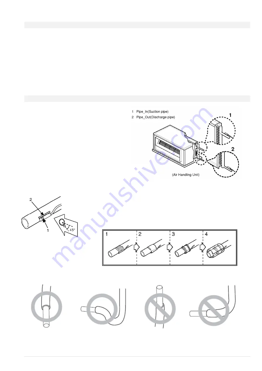
Attach thermal sensors TEMP1 (blue) and TEMP2
(red) to suitable locations on the heat exchanger
in
the HVAC system. The blue sensor is designed for
“input” of the refrigerant into the heat exchanger,
that is the small diameter pipes, and the “red”
sensor is designed for “output” of the refrigerant
from the heat exchanger - large diameter pipes.
To properly attach sensors to Cu pipes use, for
example fastening clamps to ensure proper heat
transfer to the sensor
–
see Fig.
After the sensors are attached make sure to
insulate them thermally from the environment.
Description: 1
–
the most sensitive spot of the sensor
2
–
maximises the contact between the sensor and pipe
Installation description:
Create a loop on the sensor cable in order to prevent collection of water/humidity in the sensor connection.
Notice
:
Incorrect installation of temperature sensors may result in incorrect control of the cooling process.
Incorrect installation of temperature sensors may permanently damage the refrigerant sensors.


