2020/07/23 page 10
Attention, it is necessary to observe the polarity/color of the terminals (e.g. white wire to the white terminal).
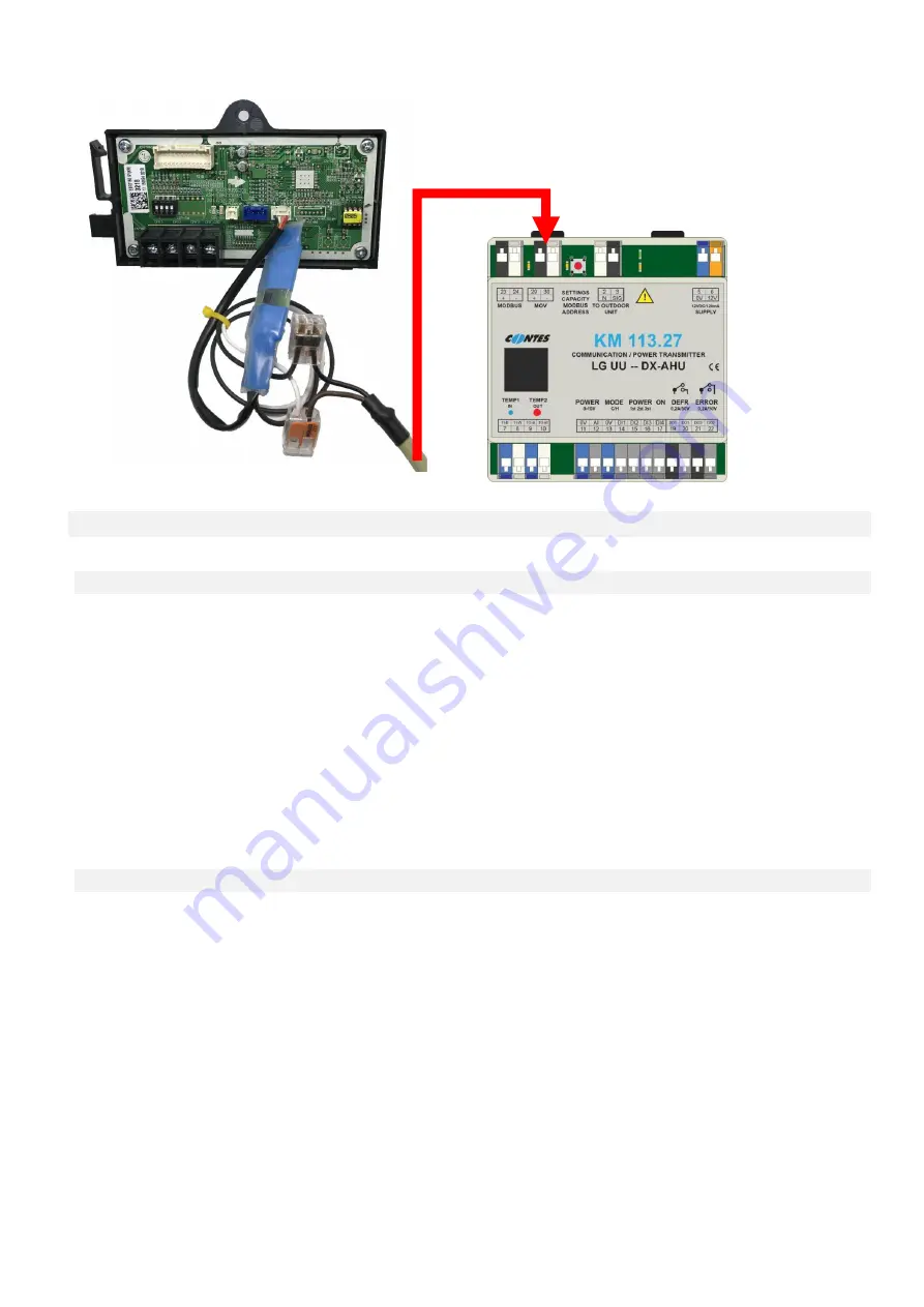
Fig.5 - Connection diagram of MOV-UU to an outdoor
compression unit UU-- and KM113.27UU
(e.g. for UU18W.UE4 unit)
5.
CONNECTION
TO
SUPERIOR
I&C
HVAC
SYSTEM
5.1 Control – descriptions, priorities
As for the external control the communication module allows you to use:
1/ “MODBUS“ communication protocol (only KM113.27UU)
2/ request on capacity through the use of 0…10V signal
3/ request on capacity through the use of contact inputs (3 max)
The communication module respects priority of external signals as follows:
If the MODBUS communication sends at least one record from the recorded registries only commands from
MODBUS will be respected (logic and analogue signals are ignored) until the power supply is turned off.
In the analogue signal is above the power output “1” the analogue input for the power value will be accepted as
the control input.
In the analogue signal is not active, the control through logic signals is respected (contacts).
MODBUS PROTOCOL CONTROL (MONITORING) (see separate section for description
)
5.2
INPUTS FOR EXTERNAL CONTROL
– digital, analogue
OPERATION ACTIVATION (ON-OFF)
Input terminals “ON” – Logic input (voltage-free contact).
When the contact "0V + D4" is closed (terminals 13 + 17) the operation of the device is allowed, when it is
opened the operation is stopped.
The current status of this input is indicated on the display by the size of the letter showing the selected
operational mode.
Example:
“cO … 24 … 24“
= operational mode “cooling “, operation is not allowed
“CO … 24 … 24“
= operational mode “cooling“, operation is allowed


