2020/07/23 page 14
POWER
7
6
5
4
3
2
1
0
A2
A1
A0
FUNCTION
7
6
5
4
3
2
1
0
RESET
OFF/ON
L1
L0
C/H
The RESET function is used for example when you need to transfer the control of hardware to signals without
the need to shut down the power supply to the unit.
When the communication is activated through the first record it is necessary to communicate more
often than during 1 minute.
(the recommended communication frequency is once every 1 to 10 second)
If writing is not repeated, the situation will be considered as a MODBUS communication error (error
Er 99).
Notice: If an error is active (ER--), the registers are automatically set to “0”.
Reading the values of the read registers is possible at any time without time limit and does not affect the
control by HW signals.
6. CONFIGURATION
AND
CONNECTION
CHECK
6.1 Setting the power code and MODBUS communication address
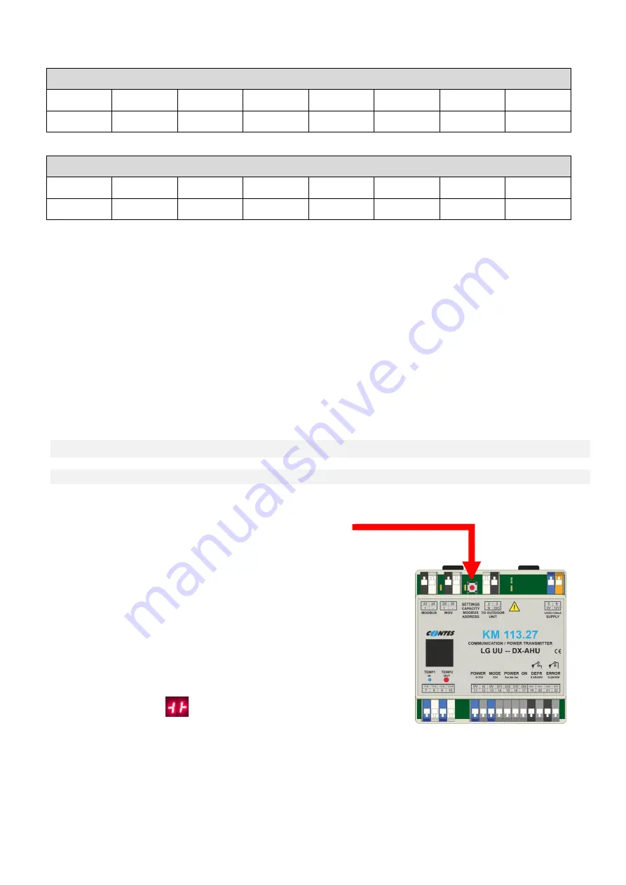
Fig.9 – Adjustment mode activation diagram
The power code and address for external control (MODBUS)
are set using the “SETTINGS” button (CAPACITY +
MODBUS)
.
Setting procedure:
ENTERING THE “SETTINGS” MODE
1.
Press the SETTINGS button while turning on the power to the
module
-
Entering the setting mode is indicated on the display by a
character
ENTERING THE “POWER CODE SETTING” MODE
2.
Hold the SETTINGS button for 5 s.
-
The display shows the set power code in
kW
.
-
The power code can be changed by shortly pressing the SETTINGS button. It changes cyclically
according to the following table


