2020/07/23 page 7
4.
INSTALLATION – CONNECTION TO THE AIR-CONDITIONING SYSTEM
4.1 MECHANICAL INSTALLATION
The communication box is to be installed near to the heat exchanger in
the HVAC system – refrigerant temperature sensors at the exchanger in
the HVAC system are connected to the module (standard cable length of
refrigerant temperature sensors on the evaporator is 3 m, sensors with a
length of 6 m - accessories on request).
The plastic box allows the module to be installed in indoor or outdoor
environments providing that safety installation procedures are observed
(the box integrity is not compromised; suitable cable glands are used). If
the box is installed outdoor, it is necessary to protect the box from direct
UV radiation (shaded area). In this case, we recommend using a box
with increased UV resistance (KM113.27UU-UV).
Preparation:
Remove the front cover from the installation box – loosen the 4 threaded
locks at the cover corners. Now you may access the connection terminals of the communication module and the
power supply source.
Have cable glands suitable for your intended application ready.
Attach the communication box to a suitable vertical plane (use the holes and covers at the rear of the box).
4.2 INSTALLATION – connection of refrigerant temperature sensors
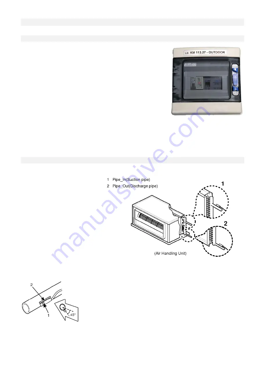
Attach thermal sensors TEMP1 (blue)
and TEMP2 (red) to suitable locations on
the heat exchanger in the HVAC
system. The blue sensor is designed for
“input” of the refrigerant into the heat
exchanger, that is the small diameter
pipes, and the “red” sensor is designed
for “output” of the refrigerant from the
heat exchanger - large diameter pipes.
To properly attach sensors to Cu pipes
use, for example fastening clamps to
ensure proper heat transfer to the
sensor – see Fig.
After the sensors are attached make sure to insulate them thermally from the environment.
Description: 1 – the most sensitive spot of the sensor
2 – maximizes the contact between the sensor and the pipe


