2020/07/23 page 8
Installation description:
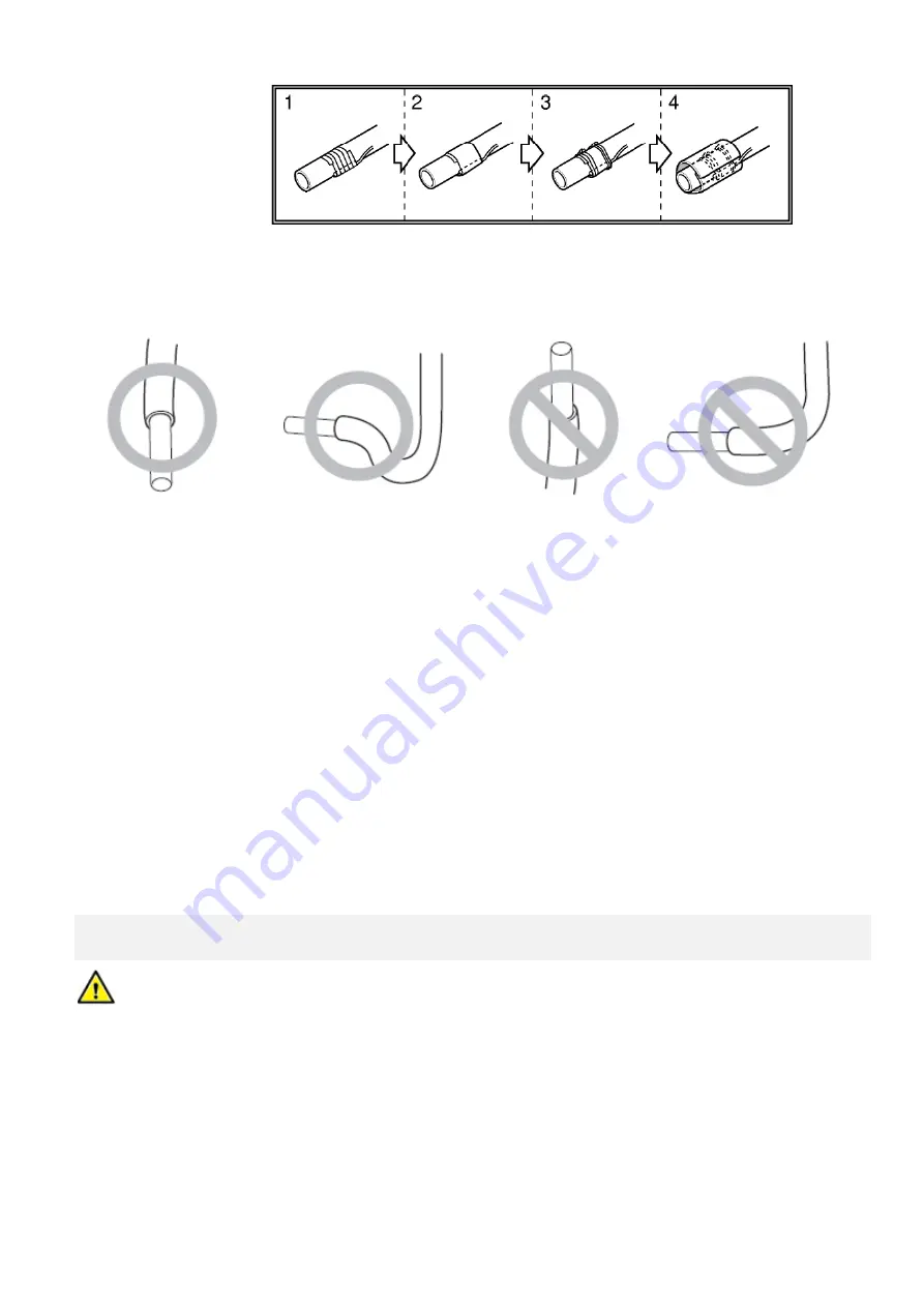
Create a loop on the sensor cable in order to prevent collection of water/humidity in the sensor connection.
Notice:
Incorrect installation of temperature sensors may result in incorrect control of the cooling process.
Incorrect installation of temperature sensors may permanently damage the refrigerant sensors.
CONNECTION OF REFRIGERANT TEMPERATURE SENSORS TO KM113.27UU MODULE
Connect the temperature sensors TEMP1 and TEMP2 to the relevant terminals on the module. Observe color
coding of the sensors – blue sensor to “TEMP1 terminals - white wire to white terminal (No. 8), red sensor to
“TEMP2“ – white wire to white terminal (No. 10)!
Sensors are delivered with standard cable length of 3 m (
sensors with longer cable length on request).
Notice:
When the temperature sensor is connected incorrectly or is defective the safety function of the communication
module is activated and the system generates corresponding error message (see the list of error messages of
the applied LG unit).
4.3 CONNECTION TO
AN OUTDOOR COMPRESSOR UNIT
– POWER SUPPLY,
COMMUNICATION
Connect a suitable power cable between the power terminals of the outdoor compressor unit (see the diagram
of the given unit) and the “supply” terminals in the communication box (terminal source “230
VAC” - “L, N”).
Connect suitable (shielded) communication cable between the outdoor compressor unit (see the diagram of the
used unit – usually terminals “N“ and “SIG“) and terminals “TO OUTDOOR UNIT” of the KM113.27UU (terminals
2+3).


