- 1-9 -
• BLACK
: This lead is for the ground connection.
• ORANGE
: This lead is for the phone line connection.
• PINK
: This lead is for the dimmer line
connection.
• RED
: This lead is for connection to the power
supply terminal when the ignition switch is
set to ACC.
• YELLOW
: This lead is for connection to the battery
(back-up) terminal from which power is
always supplied.
• BLUE
: This lead is for the power antenna
connection.
• BLUE/WHITE : This lead is for the remote amplifier on
connection.
L
R
L
R
1
2
3
4
5
6
7
8
REAR
FRONT
Connect the AUDIO OUTPUT connector of this unit to the
AUDIO INPUT connector of the Auxiliary Equipment.
Connecting to Auxiliary Equipment (Optional)
To AUDIO IN
To AUDIO IN
To AUDIO OUT
FL (Front Left)
FR (Front Right)
RL (Rear Left)
RR (Rear Right)
Speaker Connections
C
Summary of Contents for LAC-M5600
Page 11: ... 1 10 ...
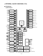
Page 18: ... 2 7 INTERNAL BLOCK DIAGRAM of ICs UPD78F0546 1 Block Diagram ...
Page 20: ... 2 9 2 Pin Descriptions ...
Page 21: ... 2 10 ...
Page 22: ... 2 11 BD3805F SCF built in sound processor 1 BLOCK DIAGRAM ...
Page 23: ... 2 12 HA13173 Multi Voltage Regulator IC ...
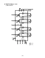
Page 24: ... 2 13 TA8275H Bipolar Liner 1 Block Diagram ...
Page 25: ... 2 14 AM5810 Motor Driver IC 1 Block Diagram ...
Page 26: ... 2 15 3 Pin Function ...
Page 32: ... BLOCK DIAGRAM WHOLE 2 21 2 22 ...
Page 33: ...2 23 2 24 BLOCK DIAGRAM CDP ...
Page 34: ...2 25 2 26 SCHEMATIC DIAGRAMS MAIN SCHEMATIC DIAGRAM ...
Page 35: ...2 27 2 28 FRONT SCHEMATIC DIAGRAM ...
Page 36: ...2 29 2 30 USB SCHEMATIC DIAGRAM ...
Page 37: ...2 31 2 32 USB SUB SCHEMATIC DIAGRAM ...
Page 38: ...2 33 2 34 CD SCHEMATIC DIAGRAM ...
Page 39: ...2 35 2 36 PRINTED CIRCUIT BOARD DIAGRAMS MAIN P C BOARD DIAGRAM BOTTOM ...
Page 41: ...2 39 2 40 CD P C BOARD BOTTOM CD P C BOARD TOP ...


