- 1-6 -
1
Remove the battery holder with a pencil or ball point pen.
2
Install the battery on the battery holder.
3
Install the battery holder back into its original position.
Notes
• Use only one CR2025 (3V) lithium battery.
• Remove the battery if the remote control is not used for a
long period of time.
• Do not leave the product in a hot or humid place.
• Do not handle the battery using metallic tools.
• Do not store the battery together with metallic materials.
• In the event of battery leakage, wipe the remote control
completely clean and install a new battery.
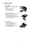
Battery installation
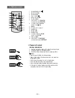
Remote Control
10
12
14
15
16
1
3
8
9
4
5
2
6
7
11
13
1
POWER [PWR] / MUTE
2
SELECTION [SEL]
3
SOURCE [SRC]
4
PLAY / PAUSE
5
INTRO SCAN [SCAN]
6
SHUFFLE [SHF]
7
• MP3 TRACK +10
• FOLDER UP [F+]
8
• CD SKIP / SEARCH
• SEEK / TUNE
9
[BAND]
10 VOLUME UP
<
<
/ DOWN
11 NUMBER [#]
12 REPEAT [RPT]
13 NUMBER [0 -9]
14 • CD SKIP / SEARCH
• SEEK / TUNE
15 DISPLAY [DISP.]
16 • MP3 TRACK -10
• FOLDER DOWN [F-]
WMA
MP3
WMA
MP3
WMA
MP3
WMA
MP3
3. Remote control
Summary of Contents for LAC-M5600
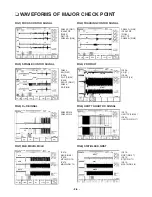
Page 11: ... 1 10 ...
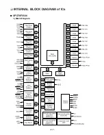
Page 18: ... 2 7 INTERNAL BLOCK DIAGRAM of ICs UPD78F0546 1 Block Diagram ...
Page 20: ... 2 9 2 Pin Descriptions ...
Page 21: ... 2 10 ...
Page 22: ... 2 11 BD3805F SCF built in sound processor 1 BLOCK DIAGRAM ...
Page 23: ... 2 12 HA13173 Multi Voltage Regulator IC ...
Page 24: ... 2 13 TA8275H Bipolar Liner 1 Block Diagram ...
Page 25: ... 2 14 AM5810 Motor Driver IC 1 Block Diagram ...
Page 26: ... 2 15 3 Pin Function ...
Page 32: ... BLOCK DIAGRAM WHOLE 2 21 2 22 ...
Page 33: ...2 23 2 24 BLOCK DIAGRAM CDP ...
Page 34: ...2 25 2 26 SCHEMATIC DIAGRAMS MAIN SCHEMATIC DIAGRAM ...
Page 35: ...2 27 2 28 FRONT SCHEMATIC DIAGRAM ...
Page 36: ...2 29 2 30 USB SCHEMATIC DIAGRAM ...
Page 37: ...2 31 2 32 USB SUB SCHEMATIC DIAGRAM ...
Page 38: ...2 33 2 34 CD SCHEMATIC DIAGRAM ...
Page 39: ...2 35 2 36 PRINTED CIRCUIT BOARD DIAGRAMS MAIN P C BOARD DIAGRAM BOTTOM ...
Page 41: ...2 39 2 40 CD P C BOARD BOTTOM CD P C BOARD TOP ...


