- 1-7 -
❏
INSTALLATION
5
4
3
1
2
6
Front panel
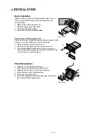
Before installing, make sure that the ignition switch is set to
OFF and remove the terminal of the car battery to avoid
short-circuiting.
1
Remove the existing receiver unit.
2
Make the necessary connections.
3
Install the installation sleeve.
4
Install the unit into the installation sleeve.
Removing the existing receiver unit.
Please remove any installation sleeves already in place for the
receiver unit in the dashboard, it must be removed.
1
Remove the rear support from the unit.
2
Remove the front panel and trim ring from the unit.
3
Insert the lever
into the hole on one side of the unit.
Perform the same operation on the other side and pull the
unit out from the mounting sleeve.
Basic Installation
1
Slide the unit into the ISO-DIN frame.
2
Install the screws removed from the old unit.
3
Slide the unit and frame into the dash opening.
4
Install the dash panel or adapter plate.
5
Install the trim ring into unit.
6
Install the faceplate by fitting the right edge into position
then pushing the left edge closed.
ISO-DIN Installation
Bend the claws
according to
the thickness
of the
dashboard
Front panel
A
A
•
•
A
Summary of Contents for LAC-M5600
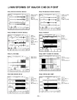
Page 11: ... 1 10 ...
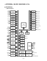
Page 18: ... 2 7 INTERNAL BLOCK DIAGRAM of ICs UPD78F0546 1 Block Diagram ...
Page 20: ... 2 9 2 Pin Descriptions ...
Page 21: ... 2 10 ...
Page 22: ... 2 11 BD3805F SCF built in sound processor 1 BLOCK DIAGRAM ...
Page 23: ... 2 12 HA13173 Multi Voltage Regulator IC ...
Page 24: ... 2 13 TA8275H Bipolar Liner 1 Block Diagram ...
Page 25: ... 2 14 AM5810 Motor Driver IC 1 Block Diagram ...
Page 26: ... 2 15 3 Pin Function ...
Page 32: ... BLOCK DIAGRAM WHOLE 2 21 2 22 ...
Page 33: ...2 23 2 24 BLOCK DIAGRAM CDP ...
Page 34: ...2 25 2 26 SCHEMATIC DIAGRAMS MAIN SCHEMATIC DIAGRAM ...
Page 35: ...2 27 2 28 FRONT SCHEMATIC DIAGRAM ...
Page 36: ...2 29 2 30 USB SCHEMATIC DIAGRAM ...
Page 37: ...2 31 2 32 USB SUB SCHEMATIC DIAGRAM ...
Page 38: ...2 33 2 34 CD SCHEMATIC DIAGRAM ...
Page 39: ...2 35 2 36 PRINTED CIRCUIT BOARD DIAGRAMS MAIN P C BOARD DIAGRAM BOTTOM ...
Page 41: ...2 39 2 40 CD P C BOARD BOTTOM CD P C BOARD TOP ...


