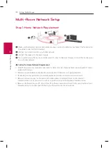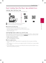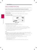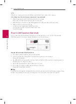
Getting Started
7
Ge
tting S
tar
ted
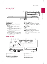
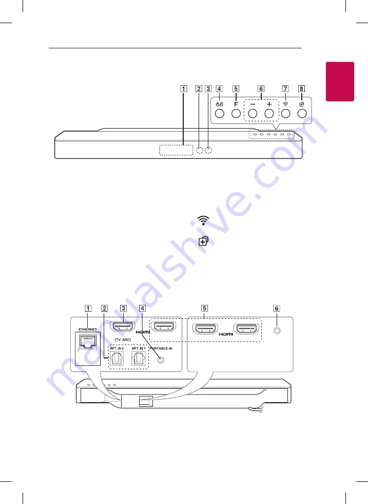
1
A
Display window
B
Remote sensor
C
LED indicator:
Shows connection status.
(Page 23)
y
White (blinking): waiting for network
connection
y
White (staying on): network connection is
completed.
y
White (Dimmed): standby mode with
network connection.
y
Green (staying on): the first group was set.
y
Red (staying on): standby mode without
network connection
D
1/!
(Standby/On)
E
F (Function):
Selects the function and input
source. (OPTICAL / HDMI IN / WI-FI / Bluetooth /
PORTABLE)
F
-
/
+
(Volume)
G
(Wi-Fi):
Connects initial MUSICflow
product to your network wirelessly.
H
(Add):
Adds the additional MUSICflow
product to your network.
(In case that one or more MUSICflow product is
connected.)
Front panel
A
ETHERNET (LAN) port
B
OPTICAL INPUT connectors
C
HDMI OUT (TV ARC) connector:
Connect to HDMI IN (ARC) on TV.
D
PORTABLE IN connector
E
HDMI IN connectors:
Connect to HDMI OUT on the external device.
F
IR BLASTER connector
Rear panel
IN 2
IN 3
IR BLASTER
OUT
IN 1


