ENGLISH
Outdoor
Indoor
Control terminal board
Control box
Control box cover
(On which the Electric
Wiring Connection is put)
Main terminal board
Cover control
Control terminal board
Main terminal board
Control terminal board
Main terminal board
Control terminal board
Cord
clamper
Cover control
A
A view
Remote
control cord
Connection
cord between
the indoor unit
and the
outdoor unit
Cord clamper
1
1
Main
power source
Switch box
Circuit Breaker
11
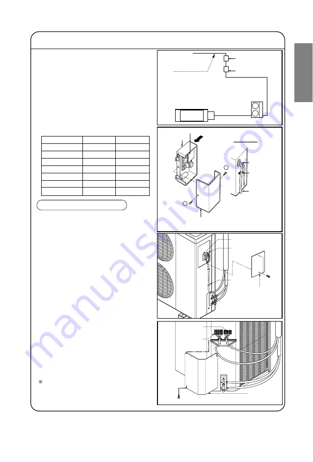
ELECTRICAL WIRING
INDOOR UNIT
• Remove the control box cover for
electrical connection between the
indoor and outdoor unit.(Remove two
screws
➀
.)
• Use the cord clamper to fix the cord.
Perform the electrical wiring work according to
the electrical wiring connection.
• All wiring must comply with local
requirements.
• Select a power source that is capable of
supplying the current required by the air
conditioner.
• Use a recognized circuit breaker
between the power source and the unit.
A disconnection device to adequately
disconnect all supply lines must be
fitted.
• Capacity of circuit breaker
WIRING CONNECTION
OUTDOOR UNIT
• Remove the control cover for wiring
connection.
• Use the cord clamper to fix the cord.
• Earthing work
Connect the cable of diameter 1.6mm
2
or more to the earthing terminal
provided in the control box and do
earthing.
Please check !!
Capacity
1 Phase
3 Phase
18K BTU/h
20A
-
24K BTU/h
25A
-
30K BTU/h
25A
-
36K BTU/h
35A
25A
42K BTU/h
40A
-
48K BTU/h
-
25A
60K BTU/h
-
25A


