ENGLISH
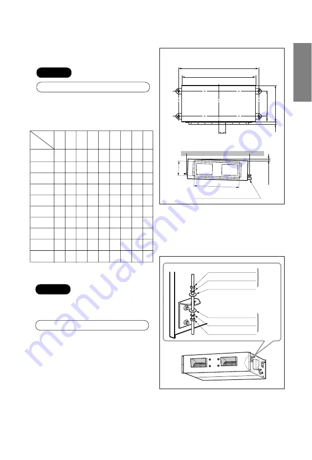
2. Indoor unit installation
■
Installation of Unit
Install the unit above the ceiling correctly.
• Apply a joint-canvas between the unit and
duct to absorb unnecessary vibration.
• Apply a filter Accessory at air return hole.
• Install the unit leaning to a drainage hole
side as a figure for easy water drainage.
• A place where the unit will be leveled and
that can support the weight of the unit.
• A place where the unit can withstand its
vibration.
• A place where service can be easily
performed.
5
CASE 1
POSITION OF SUSPENSION BOLT
CASE 2
POSITION OF CONSOLE BOLT
(Unit:mm)
Drainage hole
M10 Nut
M10 SP. washer
M10 washer
X 4
X 4
(Local
supply)
X 4
M10 Nut
M10 SP. washer
M10 washer
X 4
X 4
(Local
supply)
X 4
A
B
C
1-3 mm
D
(G)
H
I
E
F
A
B
C
D
E
F
(G)
H
I
18K BTU/h 942 880 466
54
575
30
87
750 186
24K BTU/h 942 880 466
54
575
30
87
750 186
30K BTU/h 1242 1180 492
54
600
30
87
830 186
1072 1010 492
54
600
30
87
750 186
1242 1180 492
54
600
30
87
830 186
1242 1180 492
54
600
30
87
830 186
1292 1230 650.5 54
760
30
120 1006 294
1292 1230 570.5 54
680
30
120 1006 294
1292 1230 650.5 54
760
30
120 1006 294
1292 1230 570.5 54
680
30
120 1006 294
Dimension
Capacity
36K BTU/h
(LB-C36)
36K BTU/h
(LB-F36)
42K BTU/h
48K BTU/h
(LB-B48)
60K BTU/h
(LB-B60)
48K BTU/h
(LB-E48)
60K BTU/h
(LB-E60)


