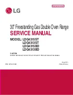
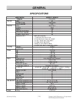
background image

1

30” Freestanding Gas Double Oven Range

SERVICE MANUAL

MODEL:   LDG4315ST 

LDG4313ST 

LDG4315BD 

LDG4313BD

CAUTION

BEFORE SERVICING THE UNIT, READ THE SAFETY PRECAUTIONS IN THIS MANUAL.

P/NO : MFL37118331

May, 2015

Printed in Korea

Internal Use Only

Summary of Contents for LDG4313BD

Page 1: ...gGasDoubleOvenRange SERVICE MANUAL MODEL LDG4315ST LDG4313ST LDG4315BD LDG4313BD CAUTION BEFORE SERVICING THE UNIT READ THE SAFETY PRECAUTIONS IN THIS MANUAL P NO MFL37118331 May 2015 Printed in Korea Internal Use Only ...

Page 2: ... lower door right side The power supply of the appliance should be turned off when it is being repaired FORWARD LG Electronics assumes no responsibility for any repairs made on our products by anyone other than Authorized Service Technicians WARNING DISCONNECT power supply cord from the outlet before servicing Replace all panels and parts before operating RECONNECT all grounding devices Failure to...

Page 3: ...oor lock oven Cooktop control lock Self clean For both Upper Lower oven Easy clean For both Upper Lower oven COMPONENT ACCESS 3 1 3 28 Component Locations 3 1 Removing the Back Control cover and Glass touch assembly 3 2 Removing the Spark Module IG Trans and Power Control Board PCB 3 3 Service instructions Signal wire 3 4 Removing the Cooktop Plate 3 5 Removing the Cooktop Parts 3 6 3 7 Removing t...

Page 4: ...Gasket 3 26 Removing a Side Panel 3 27 Removing the Oven Valve Safety Valve Gas Pressure Regulator 3 28 COMPONENT TEST 4 1 4 3 Convection Motor 4 1 Door locking Motor 4 2 Micro Switch normally open type 4 2 Oven Sensor 4 2 Door switch 4 2 Oven lamp 4 3 Igniter Type 1 2 4 3 Oven safety valve 4 3 Ignition switch 4 3 CONVERSION TO LP GAS 5 1 5 5 Composition of control 6 1 6 4 SVC TEST MODE 7 1 7 3 TR...

Page 5: ...e outlet before servicing Replace all panels and parts before operating RECONNECT all grounding devices Doing so can result in severe personal injury death or electrical shock DO NOT touch burners grates or interior surfaces of oven Heating element may be hot even though they are off Interior surfaces of an oven become hot enough to cause burns During and after use do not touch or let clothing or ...

Page 6: ...ecome hot enough to cause burns among these surfaces are oven vent openings and surfaces near these openings oven doors and windows of oven doors WARNING DO NOT store items of interest to children in cabinets above a range or on the back guard of a range Children climbing on the range to reach items could be seriously injured WARNING ALL RANGES CAN TIP INJURY TO PERSONS COULD RESULT INSTALL ANTI T...

Page 7: ... all burners are at the OFF position and all grates are cool before attempting to remove them IMPORTANT SAFETY INSTRUCTIONS SELF CLEAN OVENS Do Not Clean Door Gasket The door gasket is essential for a good seal Care should be taken not to rub damage or move the gasket Do Not Use Oven Cleaners No commercial oven cleaner or oven liner protective coating of any kind should be used in or around any pa...

Page 8: ...ch Sheet locations are shown below Nameplate is located on reverse of control panel Flip up to read nameplate from front of range Model Serial Number Location MODEL SERIAL NUMBER LABEL AND TECH SHEET LOCATIONS Tech Sheet Location On Upper Rear Cover ...

Page 9: ...re Cooktop Material Enamel of element 5 Power LR 9 1k 9 1k RR 5k 5k CR 10k 10k LF 12k 10k RF 18 5k 12 5k Oven Capacity cu ft 2 6cu ft Upper 4 3cu ft Lower Broil element 14 5k 12 5k Bake element 14 5k 12 5k Convection System 14k 12k Convection element No Upper Yes Lower of Racks LDG4315ST LDG4315BD 1 Standard 1 offset 1 Gliding LDG4313ST 2 Standard 1 offset Interior oven light auto manual Proof Yes...

Page 10: ... is left open for longer than 30 seconds during baking the fan stops Broil Mode For the Upper oven only Broil burner operates during broil mode Broil can be used to cook foods which are normally broiled Preheating is not required when using broil All foods should be turned at least once except fish which does not need to be turned Cooking Guide Refer to the Owner s manual for recommendations of ti...

Page 11: ...oast function of the lower oven 11 WARM PROOF Use to select the Warm Proof function of the lower oven 12 PIZZA Use to select the Pizza function of the lower oven 13 LOWER SELF CLEAN Use to select the Self Clean of the lower oven 14 LOWER EASY CLEAN Use to select the Easy Clean of the lower oven 15 BAKE Use to select the Bake function of the lower oven 16 LOWER TIMER ON OFF Use to set or cancel the...

Page 12: ...be turned on if self clean feature is active 5 TIMER ON OFF For Upper Lower oven To cancel timer at any time touch TIMER ON OFF NOTE 1 If you touch TIMER ON OFF once this allows you to select seconds for example if you touch 5 and 6 it means 56 seconds 2 If you touch TIMER ON OFF twice this allows you to select minutes for example if you touch 5 and 6 it means 56 minutes 6 SETTING 6 types of categ...

Page 13: ...T For the Lower oven only 11 WARM For Upper Lower oven 12 PROOF For the Lower oven only 13 LOCKOUT For Upper Lower Door lock Oven Cooktop control lock 14 SELF CLEAN For Upper Lower oven 15 EASY CLEAN For Upper Lower oven START UPPER or LOWER SELF CLEAN Once 3Hours Twice 4Hours 3 times 2Hours WARM START WARM PROOF Once WARM Press and hold the Lower CLEAR OFF pad 3 seconds In order to activate or de...

Page 14: ...g motor micro switch Burner pipe Door switch Oven light Door switch Cooktop valve Igniter broil Broil burner Upper bake burner Oven Sensor Buzzer PCB Ignition switch Door lock assembly Igniter Upper Bake Igniter Lower Bake Door lock assembly Oven Sensor Gas pressure regulator Burner body Oven light Oven valve Convection motor Lower bake burner Door locking motor micro switch NFC PCB Main PCB ...

Page 15: ...w from the controller sub assembly and remove the eyebrow 9 Remove 6 Screws of controller sub assembly 10 Pull the controller sub assembly out 11 Replace the Glass touch assembly REMOVING THE BACK CONTROL COVER AND Glass touch ASSEMBLY WARNING DISCONNECT power supply cord from the outlet before servicing Replace all panels and parts before operating RECONNECT all grounding devices Failure to do so...

Page 16: ...tion of control board 5 5 connectors of the electrode and a connector of the harness a Disconnect 6 connectors b Remove the right side of cook top barrier by removing 2 screws c Remove the 2 screws d Remove the 2 housings by your hands Buzzer PCB NFC PCB Main PCB WARNING DISCONNECT power supply cord from the outlet before servicing Replace all panels and parts before operating RECONNECT all ground...

Page 17: ...way from the wall so that you can access the rear panel 3 Remove the 8 screws from the rear control cover and remove the cover WARNING DISCONNECT power supply cord from the outlet before servicing Replace all panels and parts before operating RECONNECT all grounding devices Failure to do so can result in severe personal injury death or electric shock CAUTION Be careful when you work on the gas ran...

Page 18: ... Replace all panels and parts before operating RECONNECT all grounding devices Failure to do so can result in severe personal injury death or electric shock 1 Turn off the electrical supply and gas supply going to the range 2 Remove the griddle grates burner caps and burner heads 3 Pull knobs out 4 Remove the manifold panel by unfastening the 8 screws 5 Remove the 2 screws of cook top plate ...

Page 19: ...e 2 release tabs and slide the switch off the valve stem c Remove the valve screw and remove the valve REMOVING THE COOKTOP PARTS WARNING DISCONNECT power supply cord from the outlet before servicing Replace all panels and parts before operating RECONNECT all grounding devices Failure to do so can result in severe personal injury death or electric shock CAUTION The 2 lock tabs on each igniter swit...

Page 20: ...e page 3 5 b Remove the 2 housings and slide the switch off the valve stem c Remove the connector and remove the ignition switch 6 To remove the electrode spark plug a Remove the connector from the spark module b Stretch the electrode bracket c Remove the electrode from the burner housing ...

Page 21: ... servicing Replace all panels and parts before operating RECONNECT all grounding devices Failure to do so can result in severe personal injury death or electric shock CAUTION Use caution when handling sheet metal parts while servicing the range Some parts may have sharp edges which could result in injury 1 Turn off the electrical supply and gas supply going to the range 2 Remove the Upper door See...

Page 22: ...cal supply and gas supply going to the range 2 Remove the Upper Lower door See pages 3 19 3 20 for the procedure 3 Remove the manifold cooktop and the case assembly see page 3 5 for the procedure 4 Remove the Side panels See page 3 26 for the procedure 5 To remove the Lower door latch a Remove 4 screws to detach 2 hinge supporters of Upper oven b Remove 2 screws to widen the space between Upper Lo...

Page 23: ...ve the door switch a Remove the door switch from the range To do this squeeze tabs and use a long nose plier or a snapring plier and tap it out of the hole with a hammer b Disconnect the wires from the terminals 1 2 Wires Door Switch ...

Page 24: ...connector pull the wire toward the cavity e Remove the broil burner assembly NOTE When removing the screws make sure holding the broil burner assembly 6 To remove the igniter a Perform step 1 5 on this page b Remove the 2 screws and then remove the igniter WARNING DISCONNECT power supply cord from the outlet before servicing Replace all panels and parts before operating RECONNECT all grounding dev...

Page 25: ...emove the flame guide Remove the 2 nuts and then remove flame guide 5 To remove the bake burner assembly Remove the 1 screw and then remove the burner assembly 6 Remove the rear back cover and motor cover see step 2 4 5 on page 3 2 7 Disconnect the igniter plug 8 To remove the igniter Remove the 2 screws and then remove the igniter OVEN BOTTOM THE FRAME GUIDE AND THE UPPER BAKE BURNER ASSEMBLY For...

Page 26: ...emove 5 screws of the burner cover U remove the burner cover U 4 Remove the screw from nozzle holder of the back side 5 Remove 2 screws of the bake burner from the burner cover L and then remove bake burner 6 To remove the igniter a Perform step 1 5 on this page b Remove a screw and then remove the igniter LOWER BAKE BURNER ASSEMBLY For the Lower oven only Fan cover burner cover L burner cover U ...

Page 27: ...l the range out of its mounting location so that you can access the rear of the unit b Remove the screw from the motor cover and then remove motor cover c Disconnect the wire connection and remove the 3 screws Removing the CONVECTION FAN blade and Fan motor For the Lower oven only Nut Wire connection 3 screws CAUTION Be careful not to bend the fan blade Doing so can result in vibration noise and p...

Page 28: ...o difficult to remove the socket from the front of the oven you will have to push the socket out from the back of the unit 6 Disconnect the wires from the socket terminals Glass cover Bulb Socket Clips Viewed From Rear Panel CAUTION Be careful not to scratch or chip the oven liner paint when you remove the oven light socket in the next step WARNING DISCONNECT power supply cord from the outlet befo...

Page 29: ...d chip operates the motor 2 The cam moves the door hook connected to latch rod from unlocked position to locked position from locked Position to unlocked position 3 The cam activates the micro switch that causes the motor to stop 4 The locked status remains until the range temperature drops to approximately 500F after end of the self clean or lock out feature is reactivated The motor operates to u...

Page 30: ...t the wires from the latch drive motor and switch 5 Remove the 1 screw from the latch drive 6 Unhook the Latch rod from the cam WARNING DISCONNECT power supply cord from the outlet before servicing Replace all panels and parts before operating RECONNECT all grounding devices Failure to do so can result in severe personal injury death or electric shock CAUTION Use caution when handling sheet metal ...

Page 31: ...e connector in the back of the oven To get the connector pull the wire toward the cavity c Remove the oven sensor WARNING DISCONNECT power supply cord from the outlet before servicing Replace all panels and parts before operating RECONNECT all grounding devices Failure to do so can result in severe personal injury death or electric shock CAUTION Use caution when handling sheet metal parts while se...

Page 32: ... remove the door Step 1 Fully open the door Lift up the hinge locks toward the oven frame until they stop Step 2 Close the door to approximately 30 degrees Step 3 Press down the release buttons on each hinge on both sides of the door Step 4 Lift up the door until it is clear off the hinge CAUTION Be careful when removing and lifting the door DO NOT lift the door by the handle The door is very heav...

Page 33: ...tion Close the oven door LOWER OVEN To remove the door Step 1 Indentationedge of slot Bottom Hinge arm Step 2 Close the door to the removal position approximately five degrees Step 3 Lift the door up and out until the hinge arm is clear off of the slot Put the door on the floor Hinge arm Bottom edge of slot Indentation Hinge arm Bottom edge of slot Indentation Hinge arm Bottom edge of slot Indenta...

Page 34: ... set it aside 6 To remove the door handle a Remove 2 screws from air guide b Remove 2 screws from each handle bracket c Complete to remove the door handle WARNING DISCONNECT power supply cord from the outlet before servicing Replace all panels and parts before operating RECONNECT all grounding devices Failure to do so can result in severe personal injury death or electric shock CAUTION Use caution...

Page 35: ... 4 top liner screws See step 3 on page 3 23 b Place the door liner assembly on a padded work surface with the hinge receptacles over the edge c Lift the hinge receptacle out of the door liner slot d Lift the inner glass and bracket out of the inner cover Inner cover Hinges on both side ...

Page 36: ...sulation is not visible in the glass after the door is reassembled RESSEMBLY METHOD OF HINGE RECEPTACLE 1 Cover the inner cover with the door frame 2 Pull up the bottom of the hinge receptacle to align the hole with the hole in the frame then insert and tighten the bottom screw 3 Move the inner cover and pull the top of the hinge receptacle to align with the hole in the frame and insert the second...

Page 37: ...Step 2 b Remove 2 screw from the door bottom c Remove 4 screws from middle of door frame d Lift the door frame out of the inner cover e Remove the hinge hanger assembly and lift the inner glass and bracket out of the inner cover 2 screws Door deco Handle Screws Door deco Door deco Handle Screws Door deco Door frame 4 screws Hinge hanger assembly 4 screws Hinge hanger assembly Inner oven door glass...

Page 38: ...not visible in the glass after the door is reassembled RESSEMBLY METHOD OF HINGE HANGER 1 Cover the inner assembly into the door frame 2 Fasten 4 screws in the middle of door frame 3 Place the door liner assembly on a padded work surface with the hinge hangers over the edge 4 Fasten 2 screws in the bottom of door frame 4 screws 4 screws REASSEMBLING THE DOOR GLASS HINGE HANGER For the Lower Door ...

Page 39: ...es Door gasket Door gasket Gasket clip Liner Hole WARNING DISCONNECT power supply cord from the outlet before servicing Replace all panels and parts before operating RECONNECT all grounding devices Failure to do so can result in severe personal injury death or electric shock CAUTION Use caution when handling sheet metal parts while servicing the range Some parts may have sharp edges which could re...

Page 40: ...ck of the unit 4 Remove the rear back cover and motor cover see step 4 5 on page 3 2 5 Remove the cooktop plate see the page 3 5 for the procedure 6 Remove 10 screws from the top rear of the side panel WARNING DISCONNECT power supply cord from the outlet before servicing Replace all panels and parts before operating RECONNECT all grounding devices Failure to do so can result in severe personal inj...

Page 41: ...the oven valve 4 To remove the Gas pressure regulator a Remove 2 fittings and a gas supplier fitting b Remove 2 screws from the wool cover back WARNING DISCONNECT power supply cord from the outlet before servicing Replace all panels and parts before operating RECONNECT all grounding devices Failure to do so can result in severe personal injury death or electric shock CAUTION Use caution when handl...

Page 42: ...ugh 3 Resistance checks must be made with the power cord unplugged from the outlet and with the wiring harness or connectors disconnected Before testing any components perform the following checks WARNING Turn off the electrical supply and gas supply going to the range Replace all panels and parts before operating Reconnect all grounding devices after servicing Failure to do so can result in death...

Page 43: ...ite NOTE After checking for the continuity of switch make sure that they are connected correctly NO COM NOTE Oven sensor is so sensitive to temperature Do test after cooling down sufficiently NOTE Ω Value was tested at room temperature 77F 25 C 1 Refer to pages 3 8 3 10 for the servicing procedure 2 Measure the resistance after cooling down Multiple meter scale R x 1 Door open Door closed Continui...

Page 44: ...e Normal 45 Ω 400 Ω Room Temperature Resistance Replace if Infinite opened Normal 50 Ω 800 Ω Room Temperature Resistance Replace if Infinite opened 1 Refer to page 3 28 for servicing procedure 2 Measure the resistance after cooling down Multiple meter scale R x 1 Normal Approximately 1 3 Ω If not replace 1 Refer to pages 3 6 3 7 for servicing procedure 2 Measure the resistance by rotating the cam ...

Page 45: ...ectric shock CAUTION Use caution when handling sheet metal parts while servicing the range Some parts may have sharp edges which could result in injury CAUTION If the gas supply to the range is disconnected for any reason see the installation instructions for proper connection and safety precautions 2 CONVERT THE GAS PRESSURE REGULATOR The gas pressure regulator is located at the rear of the range...

Page 46: ...r electric shock CAUTION Use caution when handling sheet metal parts while servicing the range Some parts may have sharp edges which could result in injury 4 CONVERTING THE SURFACE BURNERS take conversion kit out of the accessory assembly see illustration the below LP orifice spuds have a orifice code on the top or the side denoting the location on the range where it is to be installed Conversion ...

Page 47: ...nge Replace all panels and parts before operating RECONNECT all grounding devices Failure to do so can result in severe personal injury death or electric shock CAUTION Use caution when handling sheet metal parts while servicing the range Some parts may have sharp edges which could result in injury 4 To prevent leakage make sure the orifice spuds are securely screwed into the gas supply tubes 5 For...

Page 48: ... flame adjustment 7 ADJUSTING THE AIR SHUTTER To adjust the air shutter on the upper bake burner for LP gas loosen the Phillips head screw and rotate the shutter fully open as shown in Fig 1 NOTE When converting the unit back to natural gas the upper bake burner s air shutter should also be fully open To adjust the air shutter on the broil burner for LP gas loosen the Phillips head screw and rotat...

Page 49: ...riginal orifices to convert the appliance to the original gas NOTE The choke for the 18 5k top burner must be removed when converting the range back to natural gas WARNING Turn off the electrical supply and gas supply going to the range Replace all panels and parts before operating RECONNECT all grounding devices Failure to do so can result in severe personal injury death or electric shock CAUTION...

Page 50: ...6 1 Composition of control 1 Wiring Diagram Main system PCB ...

Page 51: ...6 2 Composition of control Front Back Controller assembly Main PCB P N EBR80595308 Touch PCB P N EBR79627601 Buzzer PCB P N EBR76332902 NFC PCB P N EBR78789101 2 Composition of control ...

Page 52: ...6 3 Main PCB P N EBR80595308 Composition of control Touch PCB P N EBREBR79627601 CN22 CN53 CN01 CN20 CN50 CN62 CN61 CN60 ...

Page 53: ...6 4 Composition of control NFC PCB P N EBR78789101 Buzzer PCB EBR76332902 ...

Page 54: ...the Clear button 2 press the upper BAKE and BROIL buttons at the same time 3 press the upper BAKE and BROIL buttons at the same time again 4 press the NUM 0 button 5 Press the START button SEQUENCE OF SVC TEST MODE Model Option Software version Only software version is displayed at the left digits ...

Page 55: ...Whenever you input the START button the relay operation sequence should be as seen below Relay Operation Sequence Upper Bake Upper Broil Conv Heater Conv Fan Lo Conv Fan High RY 54 RY 53 RY 52 RY 62 RY 61 RY 60 DLB 1 2 3 4 5 6 7 8 9 10 11 12 Step SW Version Active load Icon ...

Page 56: ...nce Symptom Door lock fail F10 F20 Check relative part Symptom Conv Fan open F17 Check All Conv fan relays Symptom Oven lamp not operating Check the Lamp coil s resistance Symptom Oven hot F6 F16 Check All heater relays are open shorted Symptom no heating F9 F19 Check All heater relays and DLB relay are open ...

Page 57: ... code following these steps 1 Press the CLEAR button 2 Press the upper BAKE and BROIL buttons at the same time If the oven has a malfunction the Oven will show the failure Code like FIG 1 If the oven does not have any failure the Oven will look like FIG 2 NOTE After checking the F code press the CLEAR button to remove all codes FIG 1 FIG 2 Type of F Code Type of F Code Time of the failure occurren...

Page 58: ... 2 minutes on cooking except self cleaning Oven Sensor F17 Lower Conv Fan Motor Open During cook if convection fan does not operate while 1 minute cumulative time in the period of convection fan operation 1 Wiring 2 Motor s Resistance F9 Upper F19 Lower Oven No heating EXCEPT PROOF WARM and EASY CLEAN Starting temperature of 130 _ or less and the oven door is closed the oven inside temperature doe...

Page 59: ...rrect rack position See Removing and Replacing the Oven Racks in the OPERATION section Incorrect cookware is being used See Convection Bake in the OPERATION section Oven thermostat needs adjustment See Adjusting the Oven Thermostat in the OPERATION section The Clock is not set correctly See Changing Oven Settings in the OPERATION section Aluminum foil used improperly in the oven See Removing and R...

Page 60: ...Clean cycles Clean and door flash in the display The self clean cycle has been selected but the door is not closed Close the oven door Loc message appears when you want to cook The oven door is locked because the temperature inside of the oven is too high Touch the Upper Clear Off or Lower Clear Off key Oven control beeps and displays an Ferror code Check the main gas shut off valve or the oven ga...

Page 61: ...best when the soils are fully soaked and submerged in water before running the cycle If soils are not sufficiently soaked in water it can negatively affect cleaning performance Repeat the EasyClean process using sufficient water Sugar based and certain grease soils are especially hard to clean If some stubborn soils remain use the Self Clean feature to thoroughly clean your oven Soils on my oven w...

Page 62: ...eam from the water in the oven cavity As the oven heats briefly during EasyClean the water in the cavity evaporates and escapes through the oven vents How often should I use EasyClean EasyClean can be performed as often as you wish EasyClean works best when your oven is LIGHTLY soiled from such things as LIGHT grease splatter and small drops of cheese Please refer to the EasyClean section in your ...

Page 63: ...8 7 TROUBLESHOOTING 4 Troubleshooting CN01 Symptom Check Point 1 Power Failure Dead 2 No Display 1 Check Electric Wiring 2 Check the Main PCB Input Voltage with CN01 ...

Page 64: ...he beep sound Replace the Main PCB No Reconnect If defective harness replace or fix 1 No No Check the connection of Power Cord Normal Reconnect If defective harness replace or fix 2 3 Check the AC input of Main PCB Main PCB CN01 Pin 1 and 3 120V AC No Yes Replace the Main PCB 4 No Yes Check the connection of L and N at Terminal block Normal Reconnect Replace the Main PCB 5 ...

Page 65: ...8 9 TROUBLESHOOTING Conv Bake Igniter Conv Bake Safety valve E A B C D F G H I J Symptom Check Point 1 No heating 2 F9 F19 1 Check Electrical Wiring 2 Check igniter s Resistance 3 Check the Sensor ...

Page 66: ...8 10 TROUBLESHOOTING CN61 CN60 Symptom Check Point 1 No heating 2 F9 F19 1 Check Electrical Wiring 2 Check Igniter s Resistance 3 Check the Sensor ...

Page 67: ...ctric element Yes Reconnect If defective harness Replace or fix 1 Conv bake igniter Upper bake igniter Upper broil igniter Unplug the unit ICheck the resistance of each igniter Normal Measure the resistance after cooling down The resistance is shown below No Replace the failed igniter 2 yes No Upper broil igniter Upper bake igniter Conv bake igniter ...

Page 68: ...he NUM 3 button Normal Themistor value at room temp is from 70 F to 90 F as the above figure Yes Go to No 6 4 No Range Of the resistance Plug in the unit Is the resistance of thermistor normal Check Pins 4 and 5 of CN60 and pins 5 and 6 of CN61 in main PCB Normal approximately 1 09kΩ at 77 F 25 C No Replace the defected Themistor 5 Yes Unplugged the unit CN61 CN60 6 Replace the Main PCB Current Ov...

Page 69: ...8 13 TROUBLESHOOTING CN61 CN60 Symptom Check Point 1 Door Lock System Failure 2 F10 F20 1 Check Electrical Wiring 2 Check Igniter s Resistance 3 Check the Sensor ...

Page 70: ...8 14 TROUBLESHOOTING Symptom Check Point 1 Door Lock System Failure 2 F10 F20 1 Check the Electrical wiring 2 Check the Motor s Resistance 3 Check the Relay PCB Door Lock Relay ...

Page 71: ...properly after rotating twice then supervising circuit detects a Door Lock failure and the F10 or F20 error code appears Yes Go to No 2 It is normal Check the wiring Door Lock System Failure F10 or F20 1 No Plug in the unit Is the Connector disconnected or loose Check the following 1 Electric wiring of relay in Main PCB 2 Electric wiring of Locking Motor and Micro Switch 3 Electric wiring of CN60 ...

Page 72: ...l measure the resistance of door lock switch T normally open type No Replace the micro switch 3 Yes Abnormal Normal Is the resistance of the lock motor normal measure the resistance of lock motor Normal approximately 2 6kΩ Abnormal infinite or below 5 Ω No Replace the lock motor 4 Yes ...

Page 73: ...8 17 TROUBLESHOOTING CN61 CN60 Symptom Check Point 1 Sensing Fail 2 F1 F4 3 F2 F5 1 Check the Electrical Wiring 2 Check the Test Mode 3 Check the Sensor s Resistance ...

Page 74: ...f Main PCB Yes Reconnect or adjust the connection 1 Upper Sensor connection Lower Sensor connection Unplug the unit Is the resistance of thermistor normal Check Pins 4 and 5 of CN60 and pins 5 and 6 of CN61 in main PCB Normal approximately 1 09kΩ at 77 F 25 C No No Replace the defective Thermistor 2 CN61 CN61 CN60 CN60 yes ...

Page 75: ...er the test mode follow these steps 1 press the CLEAR button 2 press the upper BAKE and BROIL buttons at the same time 3 press the upper BAKE and BROIL button at the same time again 4 press the NUM 3 button Normal Thermistor value at room temp is from 70 F to 90 F Yes No Go to No 1 3 Plug in the unit 4 Current Oven Temp ...

Page 76: ...8 20 TROUBLESHOOTING Conv Bake Igniter Conv Bake Safety valve E A B C D F G H I J Symptom Check Point 1 Oven hot 2 F6 F16 1 Check the Resistance of the Relay 2 Check the Sensor s Resistance ...

Page 77: ...8 21 TROUBLESHOOTING CN61 CN60 Symptom Check Point 1 Oven hot 2 F6 F16 1 Check the Resistance of the Relay 2 Check the Sensor s Resistance ...

Page 78: ...Ω at 77 F 25 C No Replace the defective Thermistor 1 Unplug the unit CN61 CN60 Is the igniter relay normal Measure the resistance of igniter relay and Live Normal infinite Abnormal shorted No Replace the Main PCB 2 Upper Bake igniter Relay Tab 01 and Tab 54 RY54 Upper Broil igniter Relay Tab 01 and Tab 53 RY53 Convection igniter Relay Tab 01 and Tab 52 RY52 yes yes ...

Page 79: ...ROIL buttons at the same time 3 press the upper BAKE and BROIL buttons at the same time again 4 press the NUM 3 button Normal Thermistor value at room temp is from 70 F to 90 F No Replace the Main PCB 4 Plug in the unit Is the DLB relay normal Measure the resistance Normal infinite Abnormal shorted No Replace the Main PCB 3 DLB Relay Tab 62 or Tab61 and Tab 60 RY60 yes Current Oven Temp ...

Page 80: ...8 24 TROUBLESHOOTING CN62 Symptom Check Point 1 Convection Fan not working 2 F7 1 Check the Resistance of the Relay 2 Check the Motor s Resistance ...

Page 81: ...Unplug the unit CN61 Is the fan motor relay normal Measure the resistance of fan motor relay and Live Normal infinite Abnormal shorted It is also sure to disconnect the connector No Replace the Main PCB 2 Conv Fan High Conv Fan Low 1st pin of CN62 and cathode of D503 RY 61 3rd pin of CN62 and cathode of D503 RY 62 yes CN60 Fan motor Resistance Ω Approximately Fan High 25 10 Fan Low 30 10 yes ...

Page 82: ...ed or loose Check all connectors and harnesses that are associated with the convection fan Reconnect If defective harness replace or fix If the same phenomenon occurs even though after fixed connection you should replace the Main PCB Replace the Main PCB 3 ...

Page 83: ...8 27 TROUBLESHOOTING Symptom Check Point 1 Key not working 2 F3 Error 1 Check the Door Locking System 2 Check the Electrical Wiring ...

Page 84: ...Control panel With Glass Touch PCB And then check button operation using key test mode To enter the test mode follow these steps 1 press the CLEAR button 2 press the upper BAKE and BROIL buttons at the same time 3 press the upper BAKE and BROIL buttons at the same time again 4 press the NUM 7 button 5 Check the button Refer to the next page appendix 2 3 Plug in the unit If button is not operated R...

Page 85: ...essed If Key is the normal operation will be the number that corresponds to the Key displayed on the VFD 2 If the key access order was changed the buzzer make double beep sound 3 The buzzer does NOT beep when a key was accessed it would be defected How to stop Key Test mode Press 1st Bake 2nd 33th Lower CLEAR OFF Key operation Test sequence ...

Page 86: ...06 W229 8511 Model Customer Model Product Code SVC Model Model Customer Model Product Code SVC Model Model Customer Model Product Code SVC Model Model Customer Model Product Code SVC Model Model Customer Model Product Code SVC Model EV ...

Page 87: ...Upper DOOR PARTS 1009 1035 1015 1020 173U 1008 102S 173U 170L 1000 W243 W222 102S 1455 170R 102L 1035 1021 1801 EV ...

Page 88: ... EV LOWER DOOR PARTS 1009 1115 1120 102U 173L 102L 1018 1100 1704 W243 W222 W222 W101 1704 W101 102U 173L 102L 1041 1801 ...

Page 89: ...203R 2051 2006 2501 260M 2001 260B 2381 260K 2043 2042 2044 2385 CONTROLLER PARTS EV Model Customer Model Product Code SVC Model Model Customer Model Product Code SVC Model Model Customer Model Product Code SVC Model ...

Page 90: ...3964 3965 G035 3950 3951 3952 3953 381A 3980 G039 3981 G039 3982 3995 3984 3983 G045 3935 5331 3991 W323 5201 3992 3993 3994 3945 7384 3976 3977 3973 3978 3972 W294 3990 3979 3056 3402 3099 3974 G058 W294 W294 3946 3945 2441 2441 2441 2441 W293 W293 W293 W293 W293 2041 ...

Page 91: ...063 591U 5078 5078 5921 W291 546L 546R 5504 5511 4002 5535 5021 W230 5463 W291 W291 W291 W291 5516 5505 W290 5535 5451 5539 5961 5905 5502 3106 3106 5902 5515 590U 5944 594U 320U W115 5945 5409 5911 5906 5921 W291 W291 590U 5958 533U 5019 EV ...

Page 92: ...30 5505 533L W124 W233 W232 5545 320L W291 5073 5536 590L 5465 W115 W230 5021 5516 W230 5073 533H W291 W291 W291 W291 W291 W115 W291 3511 594L 6008 6000 5981 6008 8508 9384 8508 3501 3502 381X W129 3006 3947 5014 5019 5032 Model Customer Model Product Code SVC Model Model Customer Model Product Code SVC Model Model Customer Model Product Code SVC Model Model Customer Model Product Code SVC Model ...

Page 93: ......

Reviews: