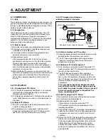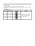
4-3 OLP (OVERLOAD PROTECTOR)
4-3-1 Definition of OLP
(1) OLP (OVERLOAD PROTECTOR) is attached to the
compressor and protects the motor by opening the
circuit to the motor if the temperature rises and
activating the bimetal spring in the OLP.
(2) When high current flows to the compressor motor, the
bimetal works by heating the heater inside the OLP, and
the OLP protects the motor by cutting off the current
flowing to the compressor motor.
4-3-2 Role of the OLP
(1) The OLP is attached to the sealed compressor used for
the refrigerator. It prevents the motor coil from being
started in the compressor.
(2) For normal operation of the OLP, do not turn the
adjustment screw of the OLP in any way.
4-4 TO REMOVE THE COVER PTC
(1) Remove the back cover of the mechanical area..
(2) Disconnect the two connectors on the top of the
compressor..
(3) Loosen two screws on compressor base.
(4) Use a flat screwdriver to pry off the cover.
(5) Assembly is the reverse order of disassembly.
- 11 -
Part
Customer part
number
Lot code/
date code
330 FBYY
-S1 BOX98
12345678
Physical
termination
part number
Electrical
characteristics
part number
No. Name
Base, phenolic
(UL 94 V-0 rated)
Movable arm support, plated steel
Stationary contact support,
plated steel
Heater support, plated steel
Heater, resistance alloy
Disc, thermostatic alloy
Movable arm, spring temper
copper alloy
Contact, movable, silver on copper
Contact, stationary, silver on copper
Slug, plated steel
Cover, polyester
(UL 94 V -0 rated)
Pin connector, plated copper alloy
(To engage 2.33/2.66 mm dia. pin)
(OVERLOAD PROTECTOR
cross section)
Figure 18
1
2
3
Summary of Contents for LFD21860ST
Page 12: ...5 CIRCUIT DIAGRAM 12 ...
Page 36: ...8 5 MAIN PWB ASSEMBLY AND PARTS LIST 8 5 1 Main PWB Assembly 36 ...
Page 37: ...8 5 2 Replacement Parts List 37 ...
Page 38: ...8 5 3 PWB Assembly Display And Parts List 38 ...
Page 39: ...8 6 PWB DIAGRAM 8 6 1 PWB Main Assembly 39 ...
Page 40: ... 40 ...


