SAFETY PRECAUTIONS ....................................................................................................................................................... 2
SPECIFICATIONS................................................................................................................................................................... 3
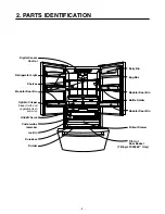
PARTS IDENTIFICATION ....................................................................................................................................................... 4
DISASSEMBLY.................................................................................................................................................................. 5-10
DOOR................................................................................................................................................................................ 5-6
DOOR ALIGNMENT..............................................................................................................................................................6
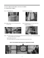
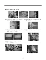
HOW TO REMOVE AND REINSTALL THE PULLOUT DRAWER.................................................................................... 7-9
ADJUSTMENT ................................................................................................................................................................. 10-11
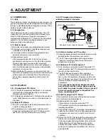
COMPRESSOR.................................................................................................................................................................. 10
PTC-STARTER................................................................................................................................................................... 10
OLP (OVERLOAD PROTECTOR)...................................................................................................................................... 11
TO REMOVE THE COVER PTC .........................................................................................................................................11
CIRCUIT DIAGRAM.............................................................................................................................................................. 12
TROUBLESHOOTING..................................................................................................................................................... 13-18
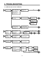
COMPRESSOR AND ELECTRIC COMPONENTS ........................................................................................................... 13
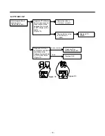
PTC AND OLP.................................................................................................................................................................... 14
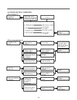
OTHER ELECTRICAL COMPONENTS ............................................................................................................................. 15
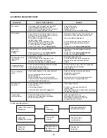
SERVICE DIAGNOSIS CHART.......................................................................................................................................... 16
REFRIGERATION CYCLE ............................................................................................................................................ 17-18
OPERATION PRINCIPLE AND REPAIR METHOD OF ICEMAKER ............................................................................. 19-22
DESCRIPTION OF FUNCTION AND CIRCUIT OF MICOM .......................................................................................... 23-40
EXPLODED VIEW AND REPLACEMENT PARTS LIST ................................................................................................... 41-
CONTENTS
- 2 -
Please read the following instructions before servicing your refrigerator.
1. Unplug the power before handling any elctrical componets.
2. Check the rated current, voltage, and capacity.
3. Take caution not to get water near any electrical components.
4. Use exact replacement parts.
5. Remove any objects from the top prior to tilting the product.
SAFETY PRECAUTIONS
Summary of Contents for LFD21860ST
Page 12: ...5 CIRCUIT DIAGRAM 12 ...
Page 36: ...8 5 MAIN PWB ASSEMBLY AND PARTS LIST 8 5 1 Main PWB Assembly 36 ...
Page 37: ...8 5 2 Replacement Parts List 37 ...
Page 38: ...8 5 3 PWB Assembly Display And Parts List 38 ...
Page 39: ...8 6 PWB DIAGRAM 8 6 1 PWB Main Assembly 39 ...
Page 40: ... 40 ...


