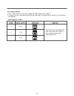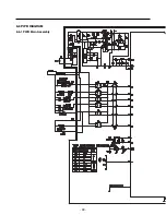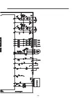
8-2-4 Load / Buzzer Drive & Open Door Detection Circuit
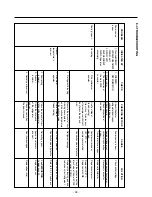
1. Load Drive Condition Check
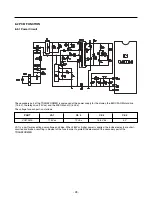
2. Fan motor driving circuit (freezer compartment fan)
1. This circuit makes standby power
0
by cutting off power supplied to ISs inside of the fan motor in the fan motor OFF.
2. This is a circuit to perform a temporary change of speed for the fan motor and applies DC voltage up to 7.5V ~ 16V to motor.
3. This circuit prevents over-driving the fan motor by cutting off power applied to the fan motor in the lock of fan motor by
sensing the operation RPM of the fan motor.
- 30 -
LOAD TYPE
COMP
NO.16
NO.11
NO.12
NO.13
NO.14
NO.15
1V or below
12V
DEFROSTING
HEATER
LAMP-F
LAMP-R
WATER
VALVE/VALVE2
FRENCH
DOOR
HEATER
Measurement Location (IC6)
Condition
ON
OFF
part
part
part
MOTOR OFF
2V or less
0V
5V
MOTOR ON
13V~15V
0V
2V~3V
a
b
c
Summary of Contents for LFD21860ST
Page 12: ...5 CIRCUIT DIAGRAM 12 ...
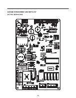
Page 36: ...8 5 MAIN PWB ASSEMBLY AND PARTS LIST 8 5 1 Main PWB Assembly 36 ...
Page 37: ...8 5 2 Replacement Parts List 37 ...
Page 38: ...8 5 3 PWB Assembly Display And Parts List 38 ...
Page 39: ...8 6 PWB DIAGRAM 8 6 1 PWB Main Assembly 39 ...
Page 40: ... 40 ...

