


LGE
LG Electronics Inc.
15/21
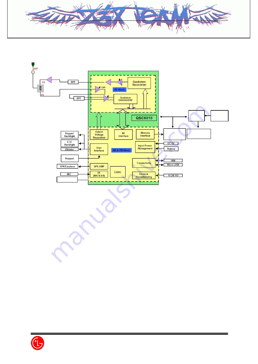
[Figure 3-1] Block Diagram Of RD6100
Camera
IC
LCD
(128*128CSTN)
Camera
(VGA)
FM Radio
MCP
64*32Mb
1.2 Description of Receive Part Circuit
1.2.1 Duplexer (DP101)
The duplexer consists of the receive part bandpass filter (BPF) and the transmit part bandpass filter
(BPF) which have the function of separating transmit/receive signals in the full duplex system using
the transmit/receive common antenna. The transmit part BPF is used to suppress noises and spurious
waves entering the receive band among transmit signals in order to prevent the drop in receive
sensitivity characteristics. The receive part BPF blocks the signals sent out from entering the receive
end in order to improve sensitivity characteristics.
Insertion loss (IL) in the transmit band is 2.8dB (Max), whereas IL in the receive band is 3.5dB (Max).
The receive band attenuation amount of transmit filter is 45dB (Min) and the transmit band attenuation
amount of receive filter is 57dB or more (Min).
Z3X-BOX.COM
Summary of Contents for LG-UD6100
Page 25: ...Circuit Diagram Z 3 X B O X C O M ...
Page 40: ...Test Points Circuit Diagram 4 3 5 UIM Trouble CON301 3 0V 3 2 1 Z 3 X B O X C O M ...
Page 46: ...Test points Circuit Diagram 4 3 8 MIC Trouble R371 C327 M301 MIC Z 3 X B O X C O M ...
Page 55: ...BACK_END_CLOCK M_CLOCK P_CLOCK VS DATA 0 Camera Locking Error Z 3 X B O X C O M ...
Page 62: ...Z 3 X B O X C O M 0 Ohm Pad 0 Ohm Pad DNI DNI ...
Page 63: ...Z 3 X B O X C O M 0 Ohm Pad 0 Ohm Pad DNI DNI ...
Page 64: ...Z 3 X B O X C O M ...
Page 65: ...Z 3 X B O X C O M ...
Page 66: ...Z 3 X B O X C O M ...


