- 4-16 -
DECK MECHANISM ADJUSTMENT
5. Audio/Control (A/C) Head Adjustment
10.9
Purpose: To insure that the tape passes accurately over the Audio and Control Tracks in
exact alignment of the both Record and Playback Modes.
Test Equipment/ Fixture
Blank Tape
Screw ) Type 5mm
Play the blank tape
Test Conditions (Mechanism Condition)
Adjustment Point
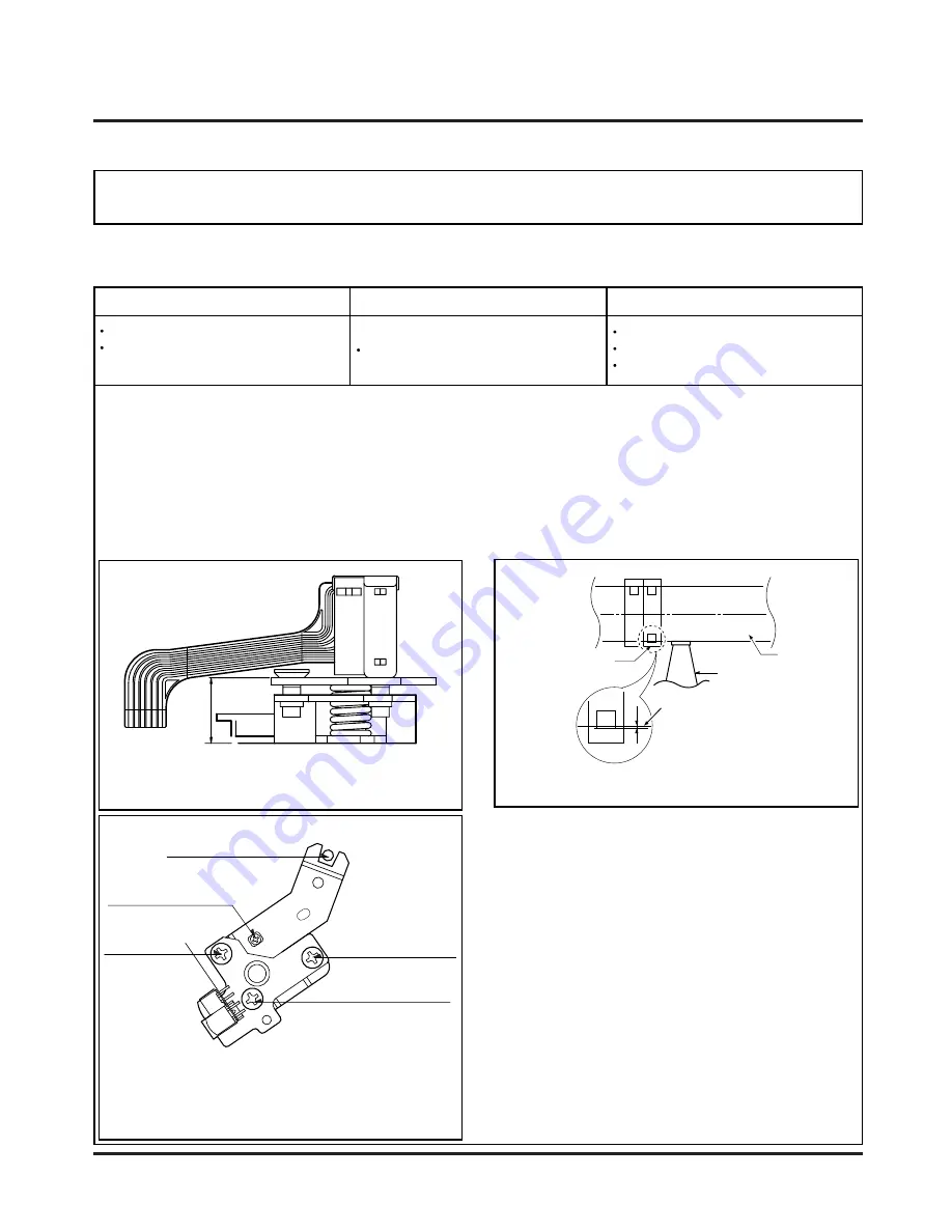
Tilt Adjustment Screw(C)
Height Adjustment Screw(B)
Azimuth Adjustment Screw(A)
Fig. C-5-1
A/C Head Base
Fig. C-5-2
Height Adjustment
Screw(B)
Tilt Adjustment
Screw(C)
Azimuth Adjustment
Screw(A)
X-Value Adjustment
Hole
Fixed Screw
Fig. C-5-3
A/C Head
Tape
Tape
0.2~0.25mm
P4
5-1. Preliminary Adjustment (Height and Tilt Adjustment)
Perform the Preliminary Adjustment, when there is no Audio Output Signal with the Alignment Tape.
1) Initially adjust the Base Assembly A/C Head as shown
Fig. C-5-1 by using the Height Adjustment Screw(B).
2) Play a blank tape and observe if the tape passes accu-
rately over the A/C Head without tape curling or folding.
3) If folding or curling is occured then adjust the Tilt
Adjustment Screw(C) while the tape is running to resem-
ble Fig. C-5-3.
4) Reconfirm the tape path after Playback about 4~5 sec-
onds.
NOTE
Ideal A/C head height occurs when the tape runs between
0.2~0.25mm above the bottom edge of the A/C Head core.
Adjustment Procedure/Diagrams
A/C Head Assembly
Summary of Contents for LH-C6230P
Page 10: ... 2 1 SECTION 2 AUDIO PART ...
Page 12: ... 3 2 VCR ELECTRICAL TROULBESHOOTING ...
Page 13: ... 3 3 ...
Page 27: ... 5 1 DVD ELECTRICAL TROUBLESHOOTING 1 Test debug flow SECTION 5 DVD PART ...
Page 28: ... 5 2 ...
Page 29: ... 5 3 ...
Page 30: ... 5 4 ...
Page 31: ... 5 5 ...
Page 32: ... 5 6 ...
Page 36: ... 5 10 2 Tray close waveform 3 Tray open waveform ...
Page 38: ... 5 12 6 LASER POWER CONTROL RELATED SIGNAL NO DISC CONDITION 7 DISC TYPE JUDGEMENT WAVEFORM ...
Page 39: ... 5 13 ...
Page 40: ... 5 14 8 FOCUS ON WAVEFORM ...
Page 41: ... 5 15 9 SPINDLE CONTROL WAVEFORM NO DISC CONDITION ...
Page 42: ... 5 16 10 TRACKING CONTROL RELATED SIGNAL System checking ...
Page 43: ... 5 17 11 RF WAVEFORM 12 MT1379 AUDIO OPTICAL AND COAXIAL OUTPUT ASPDIF ...
Page 44: ... 5 18 13 MT1379 VIDEO OUTPUT WAVEFORM 1 Full colorbar signal CVBS 2 Y ...
Page 45: ... 5 19 3 C 14 AUDIO OUTPUT FORM AUDIO DAC 1 Audio related Signal ...
Page 46: ... 5 20 MEMO ...
Page 49: ...2 2 2 3 BLOCK DIAGRAM ...
Page 50: ...2 4 2 5 AUDIO SHEMATIC DIAGRAMS U COM SCHEMATIC DIAGRAM ...
Page 51: ...2 6 2 7 FUNCTION POWER SCHEMATIC DIAGRAM ...
Page 52: ...2 8 2 9 MAIN AMP SCHEMATIC DIAGRAM ...
Page 53: ...2 10 2 11 WIRING DIAGRAM ...
Page 55: ...2 14 2 15 PRINTED CIRCUIT DIAGRAM MAINAMP FRONT P C BOARD SOLDER SIDE ...
Page 56: ...2 16 2 17 MAINAMP FRONT P C BOARD COMPONENT SIDE ...
Page 57: ...2 18 2 19 FUNCTION POWER P C BOARD SOLDER SIDE ...
Page 58: ...2 20 2 21 FUNCTION POWER P C BOARD COMPONENT SIDE ...
Page 59: ...3 17 3 18 VCR SHEMATIC DIAGRAMS SYSTEM SCHEMATIC DIAGRAM ...
Page 60: ...3 19 3 20 A AUDIO V VIDEO SCHEMATIC DIAGRAM ...
Page 62: ...3 23 3 24 TU IF ACSS SCHEMATIC DIAGRAM ...
Page 63: ...3 25 3 26 HIFI TUNER SCHEMATIC DIAGRAM ...
Page 64: ...3 27 3 28 A V JACK SCART SCHEMATIC DIAGRAM ...
Page 66: ...3 31 3 32 PRINTED CIRCUIT DIAGRAMS TUNER P C BOARD ...
Page 67: ...3 33 3 34 VCR P C BOARD ...
Page 68: ...3 35 3 36 VCR P C BOARD ...
Page 69: ...5 22 5 21 DVD PART SCHEMATIC DIAGRAMS MPEG SCHEMATIC DIAGRAM ...
Page 70: ...5 23 5 24 SERVO SCHEMATIC DIAGRAM ...
Page 71: ...5 25 5 26 AUDIO SCHEMATIC DIAGRAM ...
Page 72: ...5 27 5 28 INTERFACE SCHEMATIC DIAGRAM ...
Page 73: ...5 29 5 30 VOLTAGE SHEET IC TR ...
Page 74: ...5 31 5 32 PRINTED CIRCUIT DIAGRAM DVD P C BOARD SOLDER SIDE ...
Page 75: ...5 33 5 34 DVD P C BOARD COMPONENT SIDE ...
Page 77: ...SECTION 4 MECHANSIM OF VCR PART ...
Page 89: ... 4 12 ...
Page 101: ... 4 24 ...
Page 113: ......


