background image

- 1-3 -

NOTES REGARDING COMPACT DISC PLAYER REPAIRS

1. Preparations

1) Compact disc players incorporate a great many ICs as well as the pick-up (laser diode). These components

are sensitive to, and easily affected by, static electricity. If such static electricity is high voltage, components
can be damaged, and for that reason components should be handled with care.

2) The pick-up is composed of many optical components and other high-precision components. Care must be

taken, therefore, to avoid repair or storage where the temperature of humidity is high, where strong magnet-
ism is present, or where there is excessive dust.

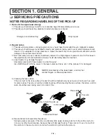
2. Notes for repair

1) Before replacing a component part, first disconnect the power supply lead wire from the unit
2) All equipment, measuring instruments and tools must be grounded.
3) The workbench should be covered with a conductive sheet and grounded.

When removing the laser pick-up from its conductive bag, do not place the pick-up on the bag. (This is
because there is the possibility of damage by static electricity.)

4) To prevent AC leakage, the metal part of the soldering iron should be grounded.
5) Workers should be grounded by an armband (1M 

)

6) Care should be taken not to permit the laser pick-up to come in contact with clothing, in order to prevent sta-

tic electricity changes in the clothing to escape from the armband.

7) The laser beam from the pick-up should NEVER be directly facing the eyes or bare skin.

Resistor
(1 Mohm)

Conductive
Sheet

Resistor
(1 Mohm)

Armband

Summary of Contents for LH-SW5100

Page 1: ...CIRCUIT DIARGAMS 2 25 SECTION 3 DVD PART ELECTRICAL TROUBLESHOOTING GUIDE 3 1 DETAILS AND WAVEFORMS ON SYSTEM TEST AND DEBUGGING 3 8 DVD PART SCHEMATIC DIAGRAMS 3 21 VOLTAGE SHEET IC TR 3 27 PRINTED CIRCUIT DIAGRAM 3 29 SECTION 4 EXPLODED VIEWS 4 1 SECTION 5 SPEAKER PART 5 1 SECTION 6 SPEAKER PART 6 1 ELECTRICAL TROUBLESHOOTING GUIDE 6 1 BLOCK DIAGRAM 6 7 SHEMATICDIAGRAMS 6 9 WIRING DIAGRAM 6 15 P...

Page 2: ...ver be touched 4 Laser beams may damage the eyes Absolutely never permit laser beams to enter the eyes Also NEVER switch ON the power to the laser output part lens etc of the pick up if it is damaged 5 Cleaning the lens surface If there is dust on the lens surface the dust should be cleaned away by using an air bush such as used for camera lens The lens is held by a delicate spring When cleaning t...

Page 3: ... replacing a component part first disconnect the power supply lead wire from the unit 2 All equipment measuring instruments and tools must be grounded 3 The workbench should be covered with a conductive sheet and grounded When removing the laser pick up from its conductive bag do not place the pick up on the bag This is because there is the possibility of damage by static electricity 4 To prevent ...

Page 4: ...harges sufficient to damage ESD devices 5 Do not use freon propelled chemicals These can generate electrical charges sufficient to damage ESD devices 6 Do not remove a replacement ESD device from its protective package until immediately before you are ready to install it Most replacement ESD devices are packaged with leads electrically shorted together by conductive foam aluminum foil or comparabl...

Page 5: ... 1 5 SPECIFICATIONS ...

Page 6: ... 1 6 LOCATION OF CUSTOMER CONTROLS FRONT PANEL DISPLAY WINDOW ...

Page 7: ... 1 7 REAR PANEL ...

Page 8: ... 1 8 REMOTE CONTROL ...

Page 9: ... AND POWER SUPPLY CIRCUIT DOES INITIAL READ WORK DOES IT PLAY YES NO YES YES OK NO YES NO NO CHECK POWER SUPPLY CIRCUIT CHECK LASER CIRCUIT CHECK TRACKING SERVO CIRCUIT TURN POWER ON CHECK FOCUS CIRCUIT CHECK DISC DOES IT OUTPUT AUDIO YES NO CHECK AUDIO CIRCUIT ELECTRICAL TROUBLESHOOTING GUIDE ...

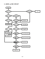
Page 10: ... 2 2 2 AUDIO µ COM CIRCUIT ...

Page 11: ...IS OK YES CHECK IF THE PN101 PN102 IS OK RECONNECTIT REFER TO NOTICE 1 CHECK IF ALL BUTTENS ARE OK YES CHECK IF THE VOLUME IS OK YES FRONT B D OK YES CHECK IF THE VFD001 PINS ARE OK CHECK PATTERN AND RESOLDERING NO YES 1 When it i sneeded to reconnect FPC cable into PN101 PN102 short ZD972 and screw chassis GND near to ZD972 2 PN101 Pins PIN2 23 0V PIN3 27 5V PIN4 5 0V PIN11 34 0V PIN20 12 0V NO N...

Page 12: ... 2 4 4 FRONT CIRCUIT 2 2 ...

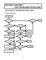
Page 13: ... 3 1 SECTION 3 DVD PART DVDTROUBLESHOOTING GUIDE 1 Power check flow ELECTRICAL TROUBLESHOOTING GUIDE ...

Page 14: ... 3 2 2 Test debug flow ...

Page 15: ... 3 3 ...

Page 16: ... 3 4 ...

Page 17: ... 3 5 ...

Page 18: ... 3 6 ...

Page 19: ... 3 7 ...

Page 20: ... 3 8 DETAILS AND W VEFORMS ON SYSTEM TEST AND DEBUGGING 1 SYSTEM 27MHz CLOCK RESET FLASH R W SIGNAL 1 MT1379 main clock is at 27MHz X501 2 MT1336 reset is high active ...

Page 21: ... 3 9 3 RS232 waveform during procedure Downloading 4 Flash R W enable signal during download Downloading ...

Page 22: ... 3 10 2 SDRAM CLOCK 1 MT1379 main clock is at 27MHz X501 3 TRAY OPEN CLOSE SIGNAL 1 Tray open close waveform ...

Page 23: ... 3 11 2 Tray close waveform 3 Tray open waveform ...

Page 24: ... 3 12 4 SLED CONTROL RELATED SIGNAL NO DISC CONDITION 5 LENS CONTROL RELATED SIGNAL NO DISC CONDITION ...

Page 25: ... 3 13 6 LASER POWER CONTROL RELATED SIGNAL NO DISC CONDITION 7 DISC TYPE JUDGEMENT W VEFORM ...

Page 26: ... 3 14 ...

Page 27: ... 3 15 8 FOCUS ON W VEFORM ...

Page 28: ... 3 16 9 SPINDLE CONTROL W VEFORM NO DISC CONDITION ...

Page 29: ... 3 17 10 TRACKING CONTROL RELATED SIGNAL System checking ...

Page 30: ... 3 18 11 RF W VEFORM 12 MT1379 AUDIO OPTICAL AND COAXIAL OUTPUT ASPDIF ...

Page 31: ... 3 19 13 MT1379 VIDEO OUTPUT W VEFORM 1 Full colorbar signal CVBS 2 Y ...

Page 32: ... 3 20 3 C 14 AUDIO OUTPUT FORM AUDIO DAC 1 Audio related Signal ...

Page 33: ... 6 1 SECTION 6 SPEAKER PART ELECTRICAL TROUBLESHOOTING GUIDE ...

Page 34: ... 6 2 ...

Page 35: ... 6 3 ...

Page 36: ... 6 4 ...

Page 37: ... 6 5 ...

Page 38: ... 6 6 MEMO ...

Page 39: ... BLOCK DIAGRAM 2 5 2 6 ...

Page 40: ...2 7 2 8 SCHEMATIC DIAGRAMS FRONT POWER SCHEMATIC DIAGRAM ...

Page 41: ...2 9 2 10 MICOM SCHEMATIC DIAGRAM ...

Page 42: ...2 11 2 12 I O SCHEMATIC DIAGRAM ...

Page 43: ...2 13 2 14 DAP SCHEMATIC DIAGRAM ...

Page 44: ...2 15 2 16 AMP SCHEMATIC DIAGRAM ...

Page 45: ...2 17 2 18 SMPS SCHEMATIC DIAGRAM ...

Page 46: ...2 19 2 20 WIRING DIAGRAM ...

Page 47: ...2 21 2 22 VOLTAGE SHEET IC TR ...

Page 48: ...2 23 2 24 ...

Page 49: ...2 25 2 26 PRINTED CIRCUIT DIAGRAMS MAIN P C BOARD SOLDER SIDE ...

Page 50: ...2 27 2 28 MAIN P C BOARD COMPONENT SIDE ...

Page 51: ...2 29 2 30 FRONT P C BOARD ...

Page 52: ...2 31 2 32 SMPS P C BOARD ...

Page 53: ...3 21 3 22 DVD PART SCHEMATIC DIAGRAMS MPEG SCHEMATIC DIAGRAM ...

Page 54: ...3 23 3 24 SERVO SCHEMATIC DIAGRAM ...

Page 55: ...3 25 3 26 INTERFACE SCHEMATIC DIAGRAM ...

Page 56: ...3 27 3 28 VOLTAGE SHEET IC TR ...

Page 57: ...3 29 3 30 PRINTED CIRCUIT DIAGRAM DVD P C BOARD SOLDER SIDE ...

Page 58: ...3 31 3 32 DVD P C BOARD COMPONENT SIDE ...

Page 59: ...IEWS CABINET AND MAIN FRAME SECTION 351 301 268 302 303 A46 A41 A26 275 266 267 A43 270 272 264 265 250 260 269 305 A47 TUNER 454 454 NOTE Refer to SECTION 6 REPLACEMENT PARTS LIST in order to look for the part number of each part ...

Page 60: ...R E009A MOTOR MECH FEEDING RF300EH 1D390 MABUCHI 015C 4680R E010A MOTOR MECH FEEDING BCZ3B51 SANKYO FOR DP7 015C 4680HP2011A MOTOR MECH PC200DG 21651C JOHNSON LOADING 017 4470R 0056A GEAR LOADING 018 4974R 0023A GUIDE UP DOWN 020 3040R D001A BASE MAIN MOLD DP 7AUDIO 021 4680R C011A MOTOR MECH SPINDLE JCL9B68 SANKYO FOR COM 022 4681R 0034D MOTOR ASSEMBLY DECK MECHA FEEDING DP 7C 7A 024 4470R 0131A ...

Page 61: ...6 7 6 8 BLOCK DIAGRAM ...

Page 62: ...6 9 6 10 SHEMATIC DIAGRAMS SCHEMATIC DIAGRAM ACC W5100 ...

Page 63: ...6 11 6 12 SCHEMATIC DIAGRAM FA W5100 ...

Page 64: ...6 13 6 14 SMPS SCHEMATIC DIAGRAM FA W5100 ...

Page 65: ...6 15 6 16 WIRING DIAGRAM ...

Page 66: ...6 17 6 18 PRINTED CIRCUIT DIAGRAM ACC W5100 P C BOARD ...

Page 67: ...6 19 6 20 FA W5100SL SR MAIN P C BOARD ...

Page 68: ...6 21 6 22 FA W5100SL SR SMPS P C BOARD ...

Page 69: ...ENTER WIRE 5M C CH A800 6401RM0089A SPEAKER ASSEMBLY 06N39EHC1319B EAW LHS 5100W NSP Non SVC Parts RUN DATA 12 FEB 04 LOCA NO PART NO DESCRIPTION SPECIFICATION REMARKS 750 3701RM0086A NET ASSEMBLY SPK LHS 5100T NET ASSY NSP 751 3790RMD001C WINDOW DECO SPK LHS 5100T MOLD ACRYL SILK NSP 752 6400WETC02A SPEAKER WOOFER 06N39EHC1319B EAW WOOFER 8OHM 753 3720RMM012A PANEL AUDIO SPK LHS W5100T MOLD FRONT...

Page 70: ...90RMD001A O WINDOW DECO SPK LHS W5100 MOLD ACRYL SILK NSP 651 3790RMD001B O WINDOW DECO SPK FAW5100 MOLD ACRYL NSP 652 6400FETC01C O O SPEAKER WOOFER 06N39EHC1319B EAW WOOFER 8OHM 653 3720RMM010A O O PANEL AUDIO SPK FA W5100SR SL MOLD HIPS GR NSP 654 6400DBHX01C O O SPEAKER TWEETER 111D10 LG03 BALHAE TWEETER DOM 655 3110RMP037A O O CASE LHS W5100SR SL MOLD HIPS GRAY NSP 656 4810RM0004A O O BRACKET...

Page 71: ...W NET ASSY NSP 952 6400WETN01A SPEAKER WOOFER 18P90EHC1391 EAW WOOFER 4 OHM 953 3091RMW058A CABINET ASSEMBLY SPK LHS D6530W WOOD CABINET NSP 954 6871RU9271F PWB PCB ASSEMBLY SUBSET AUDIO LHS D6230W SUB WOOFER 2 5M OR 955 3610RM0002A FOOT RUBBER FE 5620WE STANDARD 4 EA 962 353M050C SCREW DRAWING BH 3 5X16 FBK A900 6401RM0068A SPEAKER ASSEMBLY 18P90EHC2214 EAW LHS D6530W S NSP Non SVC Parts RUN DATA...

Page 72: ... AL 683 3508RMP050A 8 DECORATION ST W5100 PRESS BASE WEIGHT SEC 684 3508RMP050B 4 DECORATION ST W5100 PRESS BASE WEIGHT 1 6 NSP Non SVC Parts LOCA NO PART NO QTY DESCRIPTION SPECIFICATION REMARKS 663 3610RM0006A 8 FOOT RUBBER FE 5000TE PHI 20 X 3T H 664 353M051H 16 SCREW DRAWING 1 D4 0 L14 FZMY2 BLK 666 353M025R 16 SCREW DRAWING 2 D3 0 L10 0 S20C D BK WASHE 680 3040RMP013A 2 BASE LHS W5100SR SL MO...

Page 73: ... W6100 MOLD BOTTOM 557 447 059J CUSHION AUDIO FOOT CD V952 V957 562 353 645A SCREW DRAWING SPECIAL TAPPING 2X8 BK 565 6634BSTR07D ADAPTER AC DC PN003A1A 7V 400MA POWERNET 568 3890RCC062Y BOX SW 6100 SPK 1 569 3920RCE062A PACKING CASING SW6100ACCPACK 0 02 100 EPS 8 1 570 6410RKDK01A POWER CORD KJP 170 KKJ 201A KUKJE SAA 1800MM 580 6850R NAB03 CABLE USB USB TO 2 SPEAKER STRIP TYPE S NSP A40 6871RT40...

Reviews: