background image

- 1-3 -

■ 

NOTES REGARDING COMPACT DISC PLAYER REPAIRS

1. Preparations

1) Compact disc players incorporate a great many ICs as well as the pick-up (laser diode). These components

are sensitive to, and easily affected by, static electricity. If such static electricity is high voltage, components
can be damaged, and for that reason components should be handled with care.

2) The pick-up is composed of many optical components and other high-precision components. Care must be

taken, therefore, to avoid repair or storage where the temperature of humidity is high, where strong magnet-
ism is present, or where there is excessive dust.

2. Notes for repair

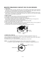
1) Before replacing a component part, first disconnect the power supply lead wire from the unit
2) All equipment, measuring instruments and tools must be grounded.
3) The workbench should be covered with a conductive sheet and grounded.

When removing the laser pick-up from its conductive bag, do not place the pick-up on the bag. (This is
because there is the possibility of damage by static electricity.)

4) To prevent AC leakage, the metal part of the soldering iron should be grounded.
5) Workers should be grounded by an armband (1M 

)

6) Care should be taken not to permit the laser pick-up to come in contact with clothing, in order to prevent sta-

tic electricity changes in the clothing to escape from the armband.

7) The laser beam from the pick-up should NEVER be directly facing the eyes or bare skin.

CLEARING MALFUNCTION

You can reset your unit to initial status if malfunction occur(button malfunction, display, etc.).
Using a pointed good conductor(such as driver), simply short the RESET jump wire on the inside of
the volume knob for more than 3 seconds.
If you reset your unit, you must reenter all its settings(stations, clock, timer)

NOTE:

1. To operate the RESET jump wire, pull the volume rotary knob and release it.
2. If you wish to operate the RESET jump wire, it is necessary to unplug the power cord.

Resistor
(1 Mohm)

Conductive
Sheet

Resistor
(1 Mohm)

Armband

RESET jump wire

VOLUME

VOLUME KNOB

DOWN

UP

Summary of Contents for LM-U2350A

Page 1: ...0 LM U4050A LMS U4050 LMS U4050W LM U5050A LMS U5050 LMS U5050W LMS U5050S SERVICE MANUAL MODEL LM U2350A LMS U2350 LM U4050A LMS U4050 LMS U4050W LM U5050A LMS U5050 LMS U5050W LMS U5050S CAUTION BEFORE SERVICING THE UNIT READ THE SAFETY PRECAUTIONS IN THIS MANUAL ...

Page 2: ...AGRAM of ICs 2 10 BLOCK DIAGRAM 2 15 SCHEMATIC DIAGRAMS 2 19 WIREING DIAGRAM 2 43 PRINTED CIRCUIT DIAGRAMS 2 45 SECTION 3 EXPLODED VIEWS CABINET AND MAIN FRAME SECTION 3 1 TAPE DECK MECHANISM A R A S RIGHT A R DECK 3 3 TAPE DECK MECHANISM A R A S LEFT A S DECK 3 5 CD MECHANISM 3 7 SECTION 4 SPEAKER PART SPEAKER PART 4 1 SECTION 5 REPLACEMENT PARTS LIST REPLACEMENT PARTS LIST 5 1 ...

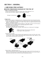
Page 3: ...ver be touched 4 Laser beams may damage the eyes Absolutely never permit laser beams to enter the eyes Also NEVER switch ON the power to the laser output part lens etc of the pick up if it is damaged 5 Cleaning the lens surface If there is dust on the lens surface the dust should be cleaned away by using an air bush such as used for camera lens The lens is held by a delicate spring When cleaning t...

Page 4: ...tive bag do not place the pick up on the bag This is because there is the possibility of damage by static electricity 4 To prevent AC leakage the metal part of the soldering iron should be grounded 5 Workers should be grounded by an armband 1M Ω 6 Care should be taken not to permit the laser pick up to come in contact with clothing in order to prevent sta tic electricity changes in the clothing to...

Page 5: ...harges sufficient to damage ESD devices 5 Do not use freon propelled chemicals These can generate electrical charges sufficient to damage ESD devices 6 Do not remove a replacement ESD device from its protective package until immediately before you are ready to install it Most replacement ESD devices are packaged with leads electrically shorted together by conductive foam aluminum foil or comparabl...

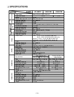
Page 6: ...y Response 42 20000 Hz Signal to noise ratio 80 dB Tape Speed 3000 3 MTT 111 NORMAL SPEED Wow Flutter 0 25 MTT 111 JIS WTD F F REW Time 120 sec C 60 Frequency Response 125 8000 Hz Signal to Noise Ratio 40 dB Channel Separation 50 dB P B 45 dB R P Erase Ratio 55dB MTT 5511 Type Bass Reflex 3Way 3 Speaker Bass Reflex 2Way 2Speaker Impedance 6Ω 24Ω Frequency Response 55 20000 Hz 60 20000 Hz Sound Pre...

Page 7: ... 1 6 ...

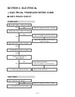
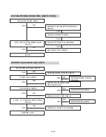
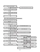
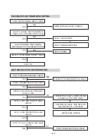
Page 8: ... 5 1VCHECK FRONT PN302 36PIN 5 1VCHECK FRONT IC306 RESET IC STATE CHECK U COM IC304 26PIN 5VCHECK SMPS TROUBLESHOOTING CONSULT CN710 CONNECTION STATE CHECK MAIN PCB PATTERN CUTTING AND SHORT CHECK IC306 INPUTVOLTAGE4V OUTPUTVOLTAGE 2 1VSTATECHECK IC306 KIA7042 CHANGE NO NO NO YES YES YES YES YES CN710 10PIN DC 33V CHECK IC304 51PIN VOLTAGE CHECK SMPS TROUBLESHOOTING CONSULT NO YES ...

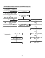
Page 9: ...L CHECK HIGH CN710 5 PIN CHECK SMPS TROUBLESHOOTING CONSULT IC304 VDD 17 46 72 90 PIN VOLTAGE CHECK P SENS TROUBLESHOOTING CONSULT Q303 STATE CHECK TR Q303 CHANGE SMPS TROUBLESHOOTING CONSULT MICOM IC304 STATE CHECK SMPS MAIN BORD TO BORD CHECK MAIN CN710 6 PIN CHECK PN302 35 PIN 5 6V MI CHECK X301 CHANGE NO NO NO NO YES YES YES YES NO NO YES YES ...

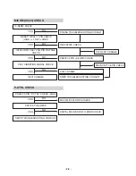
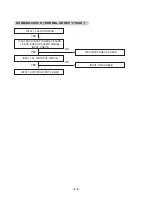
Page 10: ...PORT STATE CHECK EXPEND IC OK MUTE EXPEND IC IC305 5PIN HIGH STATE CHECK Q752 A102 STATE CHECK Q752 A102 FAULTY IS CHANGE EACH PART TR CHANGE D332 D553 D551 1SS133 CHECK D332 D553 D551 1SS133 CHANGE PCB PATTERN CHECK PCB PATTERN CHECK MICOM IC304 4 84 85 PIN CHECK CLK1 2 3 MICOM IC304 3 PIN CHECK EXPEND IC FAULTY IS CHANGE NO NO NO NO NO NO NO NO NO YES YES YES YES YES YES YES YES YES YES YES YES ...

Page 11: ...3 C LOW CHECK IC502 13 PIN REC BAIS HIGH CHECK L203 4 7MH COIL VIBRATION SIGNAL CHECK IC601 7 32 INPUT REC SIGNAL CHECK IC502 4PIN REC SW HIGH CHECK IC601 NJW1190 TROUBLESHOOTING CONSULT IC502 2 PIN 3 PIN CHECK DATA CL IC502 16 PIN VDD CHECK IC502 EXPEND IC CHANGE IC201 OUTPUT CHECK 5 26 PIN IC601 3 36PIN INPUT SIGNAL CHECK IC601 17 22 PIN OUTPUT SIGNAL CHECK DECK OUTPUT 1 1 YES YES YES YES YES YE...

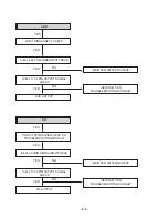
Page 12: ...IN PCB PATTERN CHECK IC601 NJW1190 TROUBLESHOOTING CONSULT MAIN PCB PATTERN CHECK IC601 NJW1190 TROUBLESHOOTING CONSULT AUX OUTPUT CD CN709 1 3PIN SIGNALCHECK CD TROUBLESHOOTINGCONSULT IC601 4 35PIN SIGNALINPUTCHECK IC601 17 22 PIN OUTPUT SIGNAL CHECK CD OUTPUT YES YES YES YES YES YES YES YES NO NO NO NO ...

Page 13: ...NGE TUNER OUTPUT MIC CN303 7 PIN MIC SIGNAL CHECK IC601 44 PIN SIGNAL CHECK OW601 PATTERN IC601 17 22 PIN OUTPUT SIGNAL CHECK CN303 4 MIC SENSE CHECK PN400 3 PIN 12V CHECK TR CHANGE MIC MUTE CHECK Q409 Q408 IC402 8 PIN SIGNAL INPUT CHECK PN400 9 VOL IN CHECK IC402 2 PIN SIGNAL INPUT CHECK PN400 10 PIN VOL OUT CHECK MIC OUTPUT MIC PCB YES YES YES YES YES YES YES YES YES YES YES YES NO NO NO NO NO ...

Page 14: ... IC601 CHANGE NO NO NO YES YES YES YES YES YES YES YES YES AMP MODULE TROUBLESHOOTING IC501 9 PIN AMP PWR HIGH CHECK EXPEND IC TROUBLESHOOTING CONSULT PROTECTION HIGH SMPS VOLTAGE AND AMP ON OFF STATE CHECK AMP MODULE CHECK MOS FET BOTH ARE READ SHORT AMP DEAD AMP MODULE CHANGE IC305 9 PIN AMP PWR HIGH CHECK IC701 11 PIN AMP ON OFF HIGH CHECK IC701 12 PIN PROTECTION LOW CHECK PN702 3 PIN PROTECTIO...

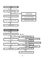
Page 15: ...204 CHANGE L203 CHANGE Q204 COLLECTOR LOW Q203 CHANGE OK REC OUTPUTCHECK AFTER FAULTY IS ICCHANGE YES YES YES YES YES YES YES YES YES YES NO REC CHECK Q252 Q202 ON R273 R223 HIGH IC601 24PIN VOLTAGE INPUT CHECK IC201 7 24 PIN INPUT CHECK IC201 10 21 PIN OUTPUT CHECK L203 2 3PIN CHECK IC202 14 PIN STATESTATE CHECK Q213 212 STATE STATECHECK DECK CHANGE IC401 EACH INPUTTUNER6 39 TAPE 7 38 CD 8 38 AUX...

Page 16: ...RMAL OR REC HIGH IC401 11 34 OUTCHECK REC INPUTCHECK CHECK INPUT LINE CHECK IC201 7 24 PIN INPUT CHECK IC201 10 21PIN OUTPUT CHECK IC401 EACH INPUTTUNER6 39 TAPE 7 38 CD 8 38 AUX 9 36PIN SIGNAL INPUT CHECK YES YES YES NO NO ...

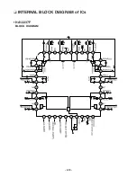
Page 17: ... 2 10 INTERNAL BLOCK DIAGRAM of ICs HA12237F BLOCK DIAGRAM ...

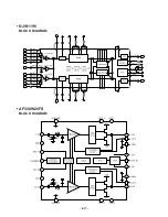
Page 18: ... 2 11 NJW1190 BLOCK DIAGRAM AF330W20FS BLOCK DIAGRAM ...

Page 19: ...1 8 L_CS I L Channel Current Sense Input 9 VCC P Positive supply Voltage 10 L_IN I L Channel Audio Input 11 STANDBY I ON OFF control 12 P_STATE O Protection State 13 R_IN I R Channel Audio Input 14 VEE P Negative supply Voltage 15 R_CS I R Channel Current Sense Input 16 AM_F2 I AM Mode control Input 2 17 R_OUT G R Channel Audio Output 18 VSS_R O R Channel Negative supply Voltage 19 R_GND P R Chann...

Page 20: ... 2 13 AF350W01FS BLOCK DIAGRAM PIN CONFIGURATION ...

Page 21: ...urrent Sense Input 4 P_CS I PMOS Current Sense Input 5 NC 6 NC 7 VEE P Negative supply Voltage 8 STANDBY I ON OFF control 9 IN I Audio Input 10 P_STATE O Protection State 11 VCC P Positive supply Voltage 12 OUT O Audio Output 13 GND G Signal Ground 14 SUBGND G Sub Ground 15 VDD P Positive supply Voltage 16 P_DO O PMOS Drain Output ...

Page 22: ...2 15 2 16 BLOCK DIAGRAM ...

Page 23: ...2 17 2 18 WMA_USB BLOCK DIAGRAM ...

Page 24: ...2 19 2 20 SCHEMATIC DIAGRAMS FRONT SCHEMATIC DIAGRAM ...

Page 25: ...2 22 2 21 MAIN SCHEMATIC DIAGRAM ...

Page 26: ...2 23 2 24 DECK SCHEMATIC DIAGRAM ...

Page 27: ...2 26 2 25 MIC SCHEMATIC DIAGRAM ...

Page 28: ...2 27 2 28 USB_AUX2_H P SCHEMATIC DIAGRAM ...

Page 29: ...2 30 2 29 WOOFER AMP SCHEMATIC DIAGRAM ...

Page 30: ...2 31 2 32 AMP SCHEMATIC DIAGRAM ...

Page 31: ...2 34 2 33 POWER SCHEMATIC DIAGRAM ...

Page 32: ...2 35 2 36 POWER SCHEMATIC DIAGRAM ...

Page 33: ...2 37 2 38 SUB POWER SCHEMATIC DIAGRAM ...

Page 34: ...2 39 2 40 CDP SCHEMATIC DIAGRAM ...

Page 35: ...2 41 2 42 USB SCHEMATIC DIAGRAM ...

Page 36: ...2 43 2 44 WIRING DIAGRAMS ...

Page 37: ... PRINTED CIRCUIT DIAGRAMS MAIN P C BOARD 2 45 2 46 ...

Page 38: ...2 47 2 48 MAIN AMP P C BOARD ...

Page 39: ...2 49 2 50 MAIN AMP P C BOARD ...

Page 40: ...2 51 2 52 FRONT P C BOARD ...

Page 41: ...2 53 2 54 CDP P C BOARD ...

Page 42: ...2 55 2 56 CDP P C BOARD ...

Page 43: ...2 57 2 58 POWER P C BOARD ...

Page 44: ...2 59 2 60 POWER P C BOARD ...

Page 45: ...2 61 2 62 SUB POWER P C BOARD ...

Page 46: ...2 63 2 64 WOOFER AMP P C BOARD ...

Page 47: ...2 65 2 66 ...

Page 48: ... 283 301 A46 275 248 A51 A56 A41 452 253 267 287 266 265 450 A54 255 251 258 250 288 303 450 A48 254 A49 256 257 270 272 273 271 A43 450 289 A00 274 269 261 262 263 264 260 268 259 450 252 286 284 302 296 305 OPTION Caution point A50 Headphone MIC USB Main array assembly pcb CABINET AND MAIN FRAME SECTION ...

Page 49: ...ARM CWL44 016 6768R GP01H DECK MECHANISM PARTS 50 093 4503 PIGEON GEAR CRL442 017 6768R AP01C DECK MECHANISM PARTS 50 239 4072 PIGEON ARM CWL44 018 6768R GP01J DECK MECHANISM PARTS 50 222 4428 PIGEON GEAR CRL442 019 6768R SP01P DECK MECHANISM PARTS 01 081 4678 PIGEON SPRING CRL4 020 6768R BP01C DECK MECHANISM PARTS 02 083 4188 PIGEON BELT FELT C 021 6768R LP01C DECK MECHANISM PARTS 50 223 4429 PIG...

Page 50: ...0 239 4072 PIGEON ARM CWL44 018 6768R GP01J DECK MECHANISM PARTS 50 222 4428 PIGEON GEAR CRL442 019 6768R SP01P DECK MECHANISM PARTS 01 081 4678 PIGEON SPRING CRL4 020 6768R BP01C DECK MECHANISM PARTS 02 083 4188 PIGEON BELT FELT C 021 6768R LP01C DECK MECHANISM PARTS 50 223 4429 PIGEON PULLEY FLYW 022 6768R VP03A DECK MECHANISM PARTS 50 093 4748 PIGEON SOLENOID AS 023 6768R GP03A DECK MECHANISM P...

Page 51: ...006A GEAR PU UP CDM H1503 167 4470RB0007A GEAR PU DOWN CDM H1503 168 4470RB0002A GEAR CAM CDM H1503 169 4860RB0002B CLAMP HOME CDM H1503 MOLD CLAMP ASSY 170 3550R 0685A COVER DECK MECHA GUIDE MOTOR CDM H15 172 3040RB0005A BASE MAIN CDM H1503 173 4510RB0001A LEVER S W CLOSE 175 4681RBA002A MOTOR ASSEMBLY HOME LOADING PULLEY 8 6 177 4470RB0001A GEAR MAIN CDM H1503 184 4900RB0002A DAMPER HOME 3CD CHA...

Page 52: ... 4 1 SECTION 4 SPEAKER SECTION MODEL LMS U2350 LMS U4050 LMS U5050 WIRE 80 865 851 864 869 866 850 852 868 853 855 854 A80 856 870 851 LEFT RIGHT 863 862 857 860 LEFT 867 859 858 WIRE 81 ...

Page 53: ... 4 2 MODEL LMS U5050W LMS U4050W 750 WIRE 71 WIRE 72 752 772 783 751 762 A70 A75 760 770 754 756 755 758 757 759 761 753 771 ...

Page 54: ... 4 3 MODEL LMS U5050S WIRE 62 WIRE 61 651 650 661 660 659 658 655 663 654 653 A60 662 WIRE 63 665 RIGHT LEFT 657 656 RIGHT LEFT ...

Page 55: ... 4 4 ...
Reviews: