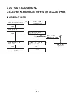
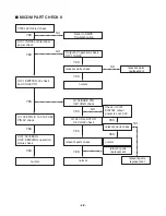
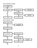
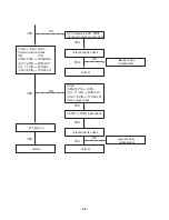
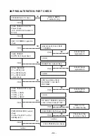
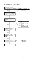
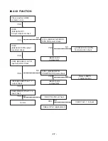
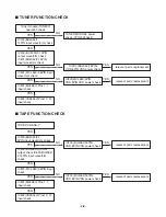
- 1-3 -
■
NOTES REGARDING COMPACT DISC PLAYER REPAIRS
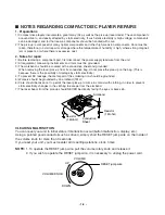
1. Preparations
1) Compact disc players incorporate a great many ICs as well as the pick-up (laser diode). These components
are sensitive to, and easily affected by, static electricity. If such static electricity is high voltage, components
can be damaged, and for that reason components should be handled with care.
2) The pick-up is composed of many optical components and other high-precision components. Care must be
taken, therefore, to avoid repair or storage where the temperature of humidity is high, where strong magnet-
ism is present, or where there is excessive dust.
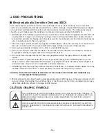
2. Notes for repair
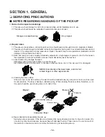
1) Before replacing a component part, first disconnect the power supply lead wire from the unit
2) All equipment, measuring instruments and tools must be grounded.
3) The workbench should be covered with a conductive sheet and grounded.
When removing the laser pick-up from its conductive bag, do not place the pick-up on the bag. (This is
because there is the possibility of damage by static electricity.)
4) To prevent AC leakage, the metal part of the soldering iron should be grounded.
5) Workers should be grounded by an armband (1M
Ω
)
6) Care should be taken not to permit the laser pick-up to come in contact with clothing, in order to prevent
static electricity changes in the clothing to escape from the armband.
7) The laser beam from the pick-up should NEVER be directly facing the eyes or bare skin.
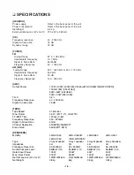
CLEARING MALFUNCTION
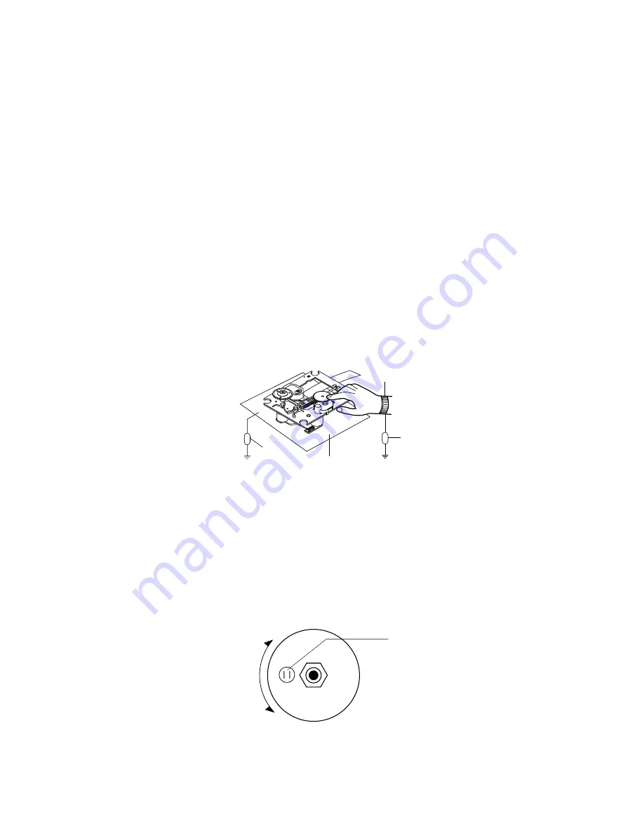
You can reset your unit to initial status if malfunction occur(button malfunction, display, etc.).
Using a pointed good conductor(such as driver), simply short the RESET jump wire on the inside of
the volume knob for more than 3 seconds.
If you reset your unit, you must reenter all its settings(stations, clock, timer)
NOTE: 1. To operate the RESET jump wire, pull the volume rotary knob and release it.
2. If you wish to operate the RESET jump wire, it is necessary to unplug the power cord.
Resistor
(1 Mohm)
Conductive
Sheet
Resistor
(1 Mohm)
Armband
RESET jump wire
VOLUME
VOLUME KNOB
DOWN
UP
Summary of Contents for LM-U360
Page 7: ... 1 6 ...
Page 20: ... 2 13 INTERNAL BLOCK DIAGRAM of ICs UTC MC4580 PIN CONFIGURATION TEST CIRCUIT ...
Page 21: ... 2 14 FAN8082D Internal Block Diagram ...
Page 22: ... 2 15 BU2090 Block diagram ...
Page 23: ... 2 16 BA3308 BA3308F BLOCK DIAGRAM BA3308 BA3308F ...
Page 24: ... 2 17 HT1200 4 SYSTEM BLOCK DIAGRAM ...
Page 25: ... 2 18 HT1200 4 FUNCTIONAL BLOCK DIAGRAM ...
Page 26: ... 2 19 CS5340 BLOCK DIAGRAM BU4052 BLOCK DIAGRAM ...
Page 27: ... 2 20 HA12237F BLOCK DIAGRAM ...
Page 28: ... 2 21 PT6324 BLOCK DIAGRAM ...
Page 43: ......
Page 53: ...2 54 2 55 PRINTED CIRCUIT DIAGRAMS MAIN P C BOARD TOP VIEW ...
Page 54: ...2 56 2 57 MAIN P C BOARD BOTTOM VIEW ...
Page 55: ...2 58 2 59 FRONT P C BOARD ...
Page 56: ...2 60 2 61 SMPS P C BOARD DECK P C BOARD BOTTOM VIEW TOP VIEW ...
Page 57: ...2 62 2 63 CD P C BOARD TOP VIEW ...
Page 58: ...2 64 2 65 CD P C BOARD BOTTOM VIEW ...
Page 59: ......
Page 65: ... 3 10 ...