82
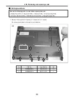
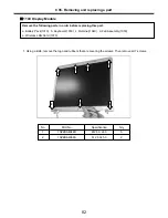
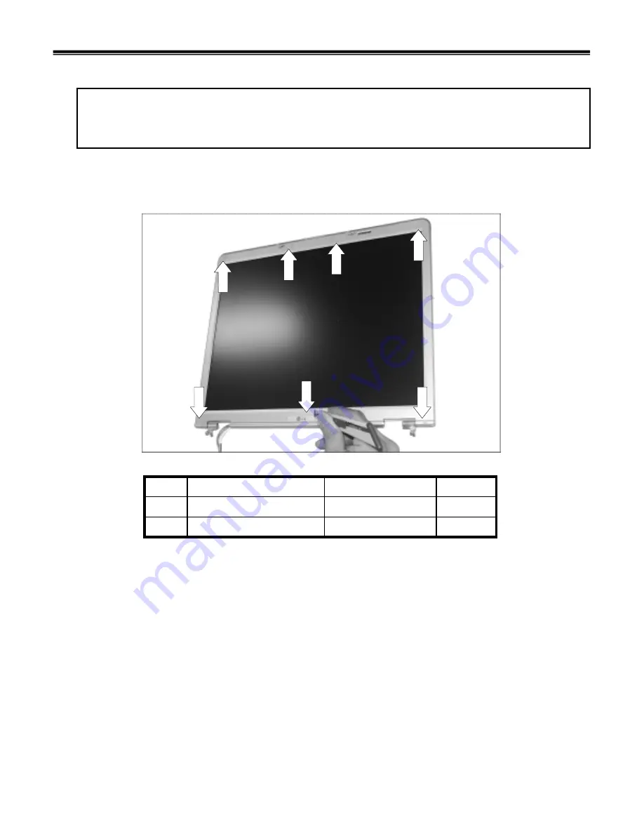
1140 Display Module
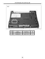
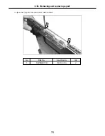
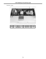
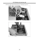
1. Using a knife, remove the logo and rubbers that are covering the screws. Then remove all 7 screws.
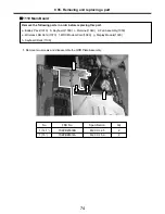
Remove the following parts in order before replacing this part.
a. Battery Pack(1010) b. Keyboard(1030) c. Retainer(1040) d. Fan Assembly(1050)
e. Wireless LAN Card (1070)
Ch5. Removing and replacing a part
1
1
1
1
2
M2.5 XL5.0
1SZZBA4068A
2
5
M2.5 X L4.0
1SZZBA4044B
1
Qty
Specification
FRU No.
No.
1
2
2
Summary of Contents for LM40
Page 1: ...0 Service Manual LM40 50 LG Electronics ...
Page 16: ...15 Model Configuration Ch3 System information ...
Page 17: ...16 System Block Diagram Ch3 System information ...
Page 56: ...55 3 Disconnect the keyboard connector Ch5 Removing and replacing a part ...
Page 59: ...58 Ch5 Removing and replacing a part ...
Page 79: ...78 8 Hold M B with your both hand and pull it up to remove Ch5 Removing and replacing a part ...
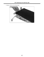
Page 88: ...87 6 Remove LCD from the LCD rear panel Ch5 Removing and replacing a part ...
Page 107: ...MKD01 MKM33 MKM31 ODD MKM32 MKD04 MKM39 MKD03 106 ...
Page 109: ...108 MKC08 MKM08 MKM32 MKM30 MKM09 MKM10 MKM11 MKM32 MKM06 15 0 MKM07 14 1 MKM30 ...
Page 112: ...111 MKC06 MKM05 MKM30 MKM28 MKM33 MKM33 MKM33 MKM34 MKM33 MKM19 MKM30 MKC01 MKC11 MKC13 ...

