LMX21981xx
REFRIGERATOR
LMX21981xx Page
47
TRAINING
MANUAL
HOW IT WORKS, continued
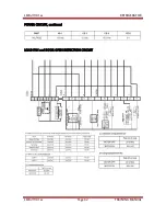
Operationally, the door monitoring switches are open when the doors are closed. When
doors are closed and monitoring switches for the refrigerator and freezer doors are open,
5 V
DC
will be measured across the control board terminals referenced above and 5 V
DC
will be measured across the open terminals of the perception section of the door
switches. When the door or doors are open, the switches will be closed. When this occurs,
zero (0) V
DC
will be measured across the door perception terminals on the control board
and across the perception terminals of the door switches.
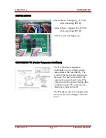
The LED section operates on 12 V
DC
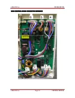
from CON 6, pins 15, 14, and 13. Pin 15 (PK) is
marked (D); this terminal is the ground reference for measuring the 12 V
DC
in the LED
section of the control board. Pin 14 (GY) is marked (E) and is the 12 V
DC
output to both
LED Modules in the refrigerator and freezer sections.
Looking closely at the LED Modules, you will see that (E) is connected to Pin 1 on the
LED Modules. This RD lead is the 12 V
DC
from the control board pin 14 (GY). Pin 2 on
the LED Module is marked (D) from the control board and is a BK wire, which is the
ground reference from Pin 15 (PK). 12 V
DC
should be present at ALL times on pins 1 and
2, RD to BK on both LED modules. This 12 V
DC
will be used to operate the LEDs in each
module when the signal voltage arrives on Pin 3 (WH).
Pin 13 (SB) on CON 6 of the main power board is a 12 V
DC
output going to each door
switch in the refrigerator and freezer sections. The 2
nd
switch in each door switch
supplies this 12 V
DC
when the door is open to the LED Modules terminal 3 (WH). When
12 V
DC
is measured on the LED module of the refrigerator or freezer from BK to WH the
LEDs will turn on. (Note: Remember there must be 12 V
DC
from BK to RD also!)
Look closely again at the refrigerator door switch. (Remember there are actually 2 of
these switches, 1 for each refrigerator door, wired as the diagram shows!) When either
refrigerator door is opened, 12 V
DC
from SB to BL/WH is sent to CON 5, pin 7 on the
main control power board. A jumper is placed on the board from CON 5, pin 7 to CON 4,
pin 1 (BL/WH). With the refrigerator door open, the 12 V
DC
leaves CON 4, pin 1
(BL/WH) and connects to the white (WH) wire on pin 3 of the refrigerator LED Module.
As with the freezer LED Module, when 12 V
DC
is present on pin 3 (WH) the LEDs will
turn on!
FINAL REMINDER: All LED DC voltages on the main power board are referenced
(measured) from CON 6, pin 15 (PK). Pin 15 is the ground reference terminal. Likewise,
on the LED modules, pin 2 (BK) is the ground reference when measuring DC voltages to
pins 1 and 3.
Summary of Contents for LMX21981 Series
Page 1: ...LG TRAINING MANUAL LG TRAINING MANUAL Four Door Refrigerator LMX21981 Fall 2008 ...
Page 6: ...LMX21981xx REFRIGERATOR LMX21981xx Page 4 TRAINING MANUAL SPECIFICATIONS ...
Page 7: ...LMX21981xx REFRIGERATOR LMX21981xx Page 5 TRAINING MANUAL ...
Page 8: ...LMX21981xx REFRIGERATOR LMX21981xx Page 6 TRAINING MANUAL PARTS IDENTIFICATION ...
Page 24: ...LMX21981xx REFRIGERATOR LMX21981xx Page 22 TRAINING MANUAL ...
Page 39: ...LMX21981xx REFRIGERATOR LMX21981xx Page 37 TRAINING MANUAL ICEMAKER SERVICE BULLETIN ...
Page 40: ...LMX21981xx REFRIGERATOR LMX21981xx Page 38 TRAINING MANUAL ...
Page 41: ...LMX21981xx REFRIGERATOR LMX21981xx Page 39 TRAINING MANUAL ...
Page 59: ...LMX21981xx REFRIGERATOR LMX21981xx Page 57 TRAINING MANUAL CIRCUIT DIAGRAM ...
Page 61: ...LMX21981xx REFRIGERATOR LMX21981xx Page 59 TRAINING MANUAL ERROR CODES ...
Page 65: ...LMX21981xx REFRIGERATOR LMX21981xx Page 63 TRAINING MANUAL OPEN DOOR DETECTION CIRCUIT CHECK ...
Page 68: ...LMX21981xx REFRIGERATOR LMX21981xx Page 66 TRAINING MANUAL DISPENSER DRIVE PWB ASSEMBLY ...
Page 69: ...LMX21981xx REFRIGERATOR LMX21981xx Page 67 TRAINING MANUAL EXPLODED VIEWS ...
Page 70: ...LMX21981xx REFRIGERATOR LMX21981xx Page 68 TRAINING MANUAL EXPLODED VIEWS continued ...
Page 71: ...LMX21981xx REFRIGERATOR LMX21981xx Page 69 TRAINING MANUAL EXPLODED VIEWS continued ...
Page 72: ...LMX21981xx REFRIGERATOR LMX21981xx Page 70 TRAINING MANUAL EXPLODED VIEWS continued ...
Page 73: ...LMX21981xx REFRIGERATOR LMX21981xx Page 71 TRAINING MANUAL EXPLODED VIEWS continued ...
Page 74: ...LMX21981xx REFRIGERATOR LMX21981xx Page 72 TRAINING MANUAL EXPLODED VIEWS continued ...
Page 75: ...LMX21981xx REFRIGERATOR LMX21981xx Page 73 TRAINING MANUAL EXPLODED VIEWS continued ...
Page 76: ...LMX21981xx REFRIGERATOR LMX21981xx Page 74 TRAINING MANUAL TEMPERATURE RESISTANCE CHART ...
Page 77: ......


