
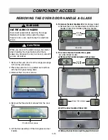


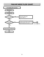
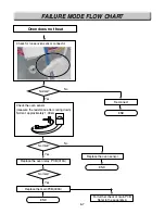


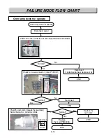

1. Refer to page 3-4 for the servicing procedure
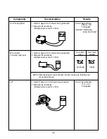
2. Set the Multiple meter scale to the R x1
3. Disconnect wires from cook-top elements
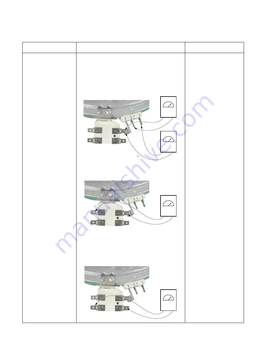
4. Touch the ohmmeter test leads to the (E1 & 1A)
and (E2 & 1A) the meter should indicate :
- (E1 & 1A)
32
Ω
± 10%
- (E2 & 1A)
55
Ω
± 10%
5. Touch the ohmmeter test leads to limiter
terminals 1A and 2A.the meter should indicate
continuity (0
Ω
)
6. Touch the ohmmeter test leads to limiter
terminals 1B and 2B.
With the temperature below 150˚F, the meter
should indicate an open circuit(infinite).
With the temperature above 150˚F, the meter
should indicate continuity (0
Ω
).
4-8
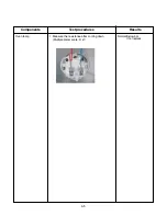
Dual surface element
: Right Front(RF)
Components
Test procedures
Results
Normal: Approximately 32
Ω
Normal: Approximately 55
Ω
Normal: continuity
(below 0.5
Ω
)
If not replace
Below 150˚F
open circuit(infinite).
Above 150˚F
continuity (0
Ω
)
1A
E2
E1
2A
1A
2B
1B
Summary of Contents for LRE30451
Page 1: ...Service Digital Appliance TRAINING MANUAL ELECTRIC RANGE LRE30451 LRE30755 ...
Page 8: ......
Page 9: ......
Page 11: ...j j j j LRE30451 LRE30755 ...
Page 67: ...8 1 APPENDIX A SCHEMATIC DIAGRAM OF PCB ...
Page 73: ...10 3 WARMNING DRAWER SELF CLEANING For Model LRE30755SW SB ST ...
Page 74: ...10 4 CLOCK DISPLAY ON CR Warming Zone CONV BAKE CONV ROAST For Model LRE30755SW SB ST ...
Page 90: ......
Page 91: ......
Page 92: ......