


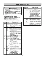


6-4
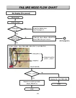
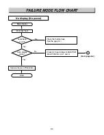
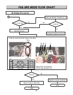
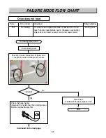
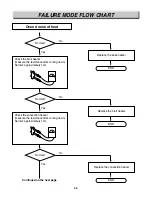
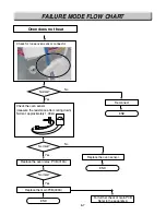
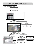
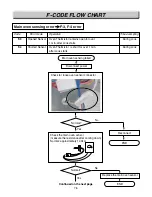
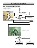
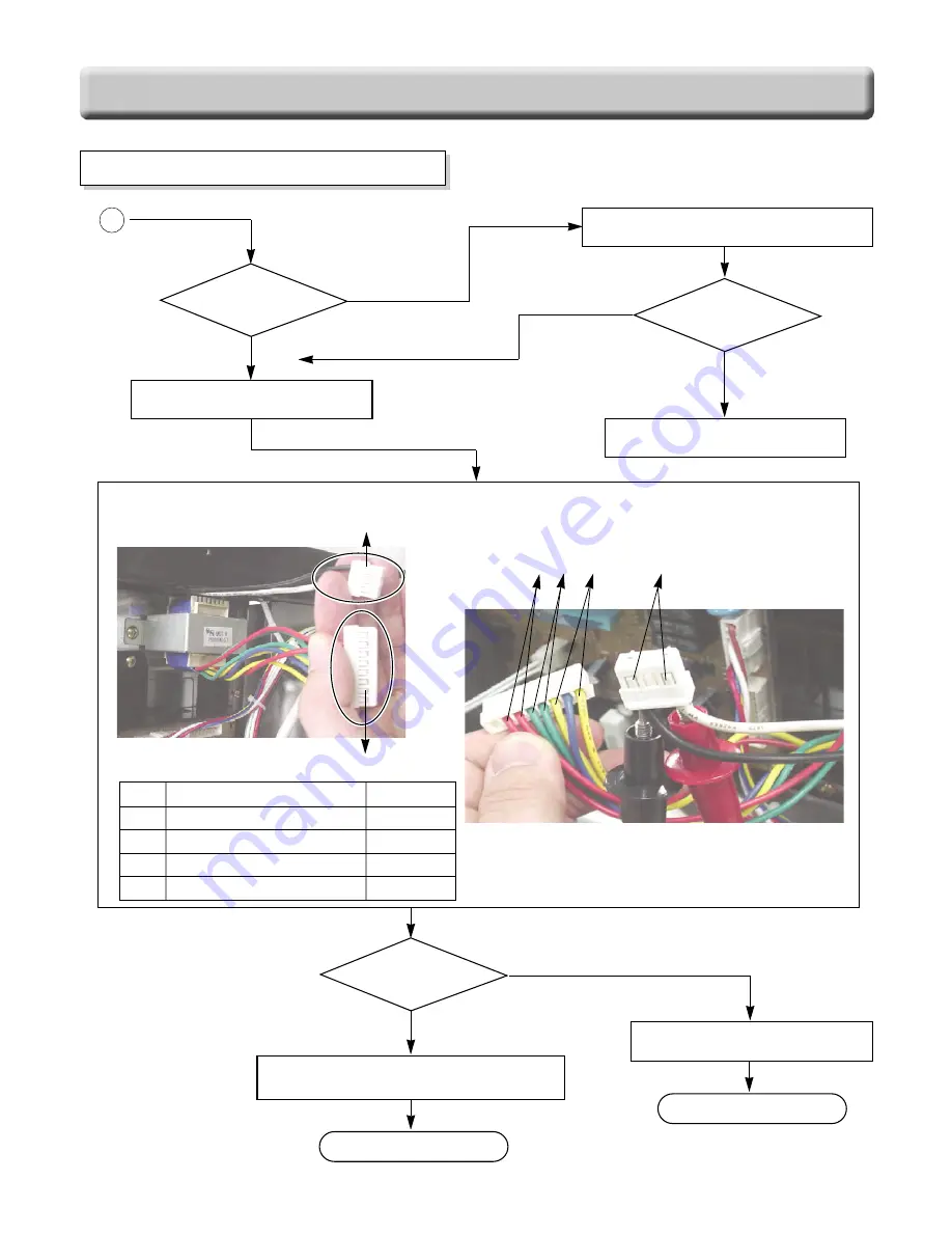
FAILURE MODE FLOW CHART
No display (No power)
No
Yes
Yes
Is it 120V AC?
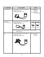
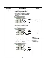
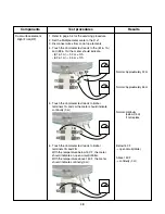
Check the harness of between L1~N
Disconnect power
No
Normal?
Replace the defective harness
1
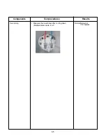
Check the power transformer (Refer to the below)
measure LVT coil resistance
(Normal: approximately Fig.1)
Primary
S3 S2 S1
P
Secondary
Fig.1
Side
Lead Color
DCR(
Ω
)
P
S1
S2
S3
black ~ white
yellow ~ blue ~ yellow
green ~ green
red ~ red
25 ~ 28
4.2 ~ 4.9
1.5 ~ 1.8
1.1 ~ 1.3
Replace the Main PCB(009A)
Normal?
END
Replace the power transformer
END
No
Yes
Summary of Contents for LRE30451
Page 1: ...Service Digital Appliance TRAINING MANUAL ELECTRIC RANGE LRE30451 LRE30755 ...
Page 8: ......
Page 9: ......
Page 11: ...j j j j LRE30451 LRE30755 ...
Page 67: ...8 1 APPENDIX A SCHEMATIC DIAGRAM OF PCB ...
Page 73: ...10 3 WARMNING DRAWER SELF CLEANING For Model LRE30755SW SB ST ...
Page 74: ...10 4 CLOCK DISPLAY ON CR Warming Zone CONV BAKE CONV ROAST For Model LRE30755SW SB ST ...
Page 90: ......
Page 91: ......
Page 92: ......