background image

Summary of Contents for LRE30451S
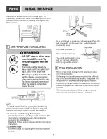
Page 1: ...Website http us lge com Electric Range LRE30955S LRE30855S LRE30755S LRE30451S these instructions thoroughly before i taJJi_ Bdoperafingtherange JJJJJii_ P No MFL37118101 ...

Page 2: ...wer cord or a 3 wire conduit has to be connected to the middle post of the main terminal block The remaining two wires of the power cord or conduit have to be connected to the outside posts of the main terminal connection block Failure to do so can result in electrical shock severe personal injury or death Only a 4 conductor power supply cord kit rated 120 240 volts 50 amperes and marked for use w...

Page 3: ...rning codes and ordinances Be sure to leave these instructions with the consumer NOTE Keep these instructions with your owner s manual for future reference As when using any appliance generating heat there are certain safety precautions you should follow Be sure your range is installed and grounded properly by a qualified installer or service technician Make sure the wall coverings around the rang...

Page 4: ... height 76 2cm _ A 30 76 2 cm For U S A 30 76 2 cm 31 78 7 cm For CANADA FIGURE 1 Cabinet storage space located above the surface units should be avoided Install a range hood that projects horizontally a minimum of 5 inches beyond the bottom of the cabinets If cabinet storage is to be provided The risk of burns or fire by reaching over the heated surface elements can be reduced 1 36 91 4cm o 30 76...

Page 5: ...re a 4 conductor UL listed range cord or 4 wire conduit connection Specified power supp y cord kit rating Range rating watts 120 240 volts 120 208 volts 3 wire 3 wire Specifiedrating of power supply cord kit amperes 8 750 16 500 7 801 12 500 40 or 50A 16 501 22 500 12 501 18 500 50 3 4 Wire electrical wall Receptacle Diameter inches of Range connection Opening Power cord Conduit 13 J 1 13 J 1 FIGU...

Page 6: ... it Refer to Figure 7 You must install the power cord with a strain relief 1 Remove the lower 3 screws from the terminal block and retain them Refer to Figure 8 2 Insert the 3 screws through each power cord terminal ring and into the lower terminals of the terminal block Make sure that the center wire white neutral is connected to the center lower position of the terminal block 3 Tighten 3 screws ...

Page 7: ...rminal block Tighten 3 screws securely into the terminal block 5 Go to page 9 4 wire connection Black White Red block strap _ strap and discard 7 c Ground screw_Conduit connection plate FIGURE 9 Install the conduit as follows Remove the Conduit connection plate from the rear of drawer body and rotate it as shown in Figure 5 The conduit hole 1 must be used First prepare conduit wires as shown in Fi...

Page 8: ... 12 Do not discard any screws 4 Attach the ground bare wire end to range frame and secure it in place with the ground screw Refer to figure 12 5 Insert the bare wire white neutral end through the center terminal block opening 6 Insert the two side bare wire ends into the left and the right terminal block opening Tighten the 3 screws securely into the terminal block approximately 35 50 IN LB 7 Go t...

Page 9: ...t check direction After check direction 2 _ If the spirit level doesn t show level on the rack adjust the leveling legs with a wrench I FINAL INSTALLATION Move range close enough to the opening to plug into the receptacle Slide range into position insuring that the left back leg slides under the anti tip bracket Range will sit 0 away from the back wall when properly installed Carefully tip range f...

Page 10: ......

Reviews: