6-1
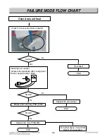
FAILURE MODE FLOW CHART
Check voltage – Main PCB(002E) CN14 (Pin 10 and 12)
No display (No power)
Blank display
Enter key input
Yes
No
Yes
Some beep
sound?
Cook-top display
blank?
Check AC input voltage of Main PCB
- Main PCB CN3 (pin 1 and 3)
Replace the cook-top display PCB(010F)
(-)4.5V ~ (-)5.5V ?
END
Replace the main PCB(002E)
END
1
CN14(Pin 10 and 12)
The voltage should
be (-)4.5V ~ (-)5.5V
Main PCB(002B)
No
Yes
No
Check the thermal fuse
(See the page 3-1)
(Go to page 6-3)


