
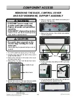

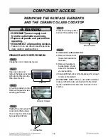


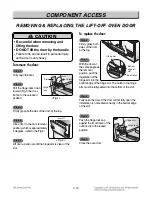


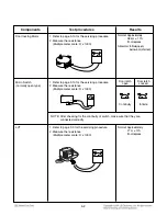


1. Unplug range or disconnect power.
2. Pull the range out of its mounting location so that
you can access the rear of the unit.
3. Remove the rear panel from the unit.
(See step 3 on page 3-2 for procedure)
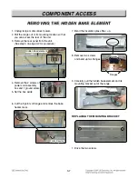
4. Remove the 2 screws of
power cord assembly
box and 1 ground screw.
5. Set the box aside
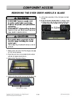
6. Cut the 9 points of flange and remove the bake
heater cover.
3-7
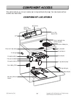
COMPONENT ACCESS
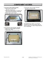
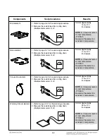
7. Bend the insulation glass fiber up.
8. Remove two screws
and bend up two flanges
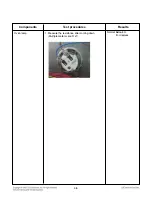
9. Carefully pull the hidden bake element and its
mounting bracket out of the range.
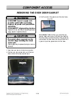
REPLACING THE MOUNTING BRACKET
1. Drive the two screws
REMOVING THE HIDDEN BAKE ELEMENT
REMOVING THE HIDDEN BAKE ELEMENT
Hidden bake element
Hidden bake element
Hidden bake element
Hidden bake element
Hidden bake element
Hidden bake element
Hidden bake element
Hidden bake element
Hidden bake element
Hidden bake element
Hidden bake element
Hidden bake element
Hidden bake element
Hidden bake element
Hidden bake element
Hidden bake element
Hidden bake element
Hidden bake element
Hidden bake element
Hidden bake element
Hidden bake element
Hidden bake element
Hidden bake element
Hidden bake element
Hidden bake element
Hidden bake element
Hidden bake element
Hidden bake element
Hidden bake element
Hidden bake element
Total 9 points
Total 9 points
Total 9 points
Total 9 points
Total 9 points
Total 9 points
Total 9 points
Total 9 points
Total 9 points
Total 9 points
Total 9 points
Total 9 points
Total 9 points
Total 9 points
Total 9 points
Total 9 points
Total 9 points
Total 9 points
Total 9 points
Total 9 points
Total 9 points
Total 9 points
Total 9 points
Total 9 points
Total 9 points
Total 9 points
Total 9 points
Total 9 points
Total 9 points
Total 9 points
Screw
Screw
Screw
Screw
Screw
Screw
Screw
Screw
Screw
Screw
Screw
Screw
Screw
Screw
Screw
Screw
Screw
Screw
Screw
Screw
Screw
Screw
Screw
Screw
Screw
Screw
Screw
Screw
Screw
Screw
Flanges