3-14
COMPONENT ACCESS
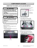
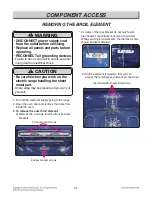
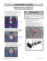
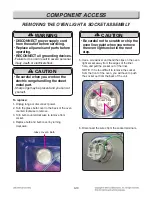
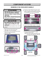
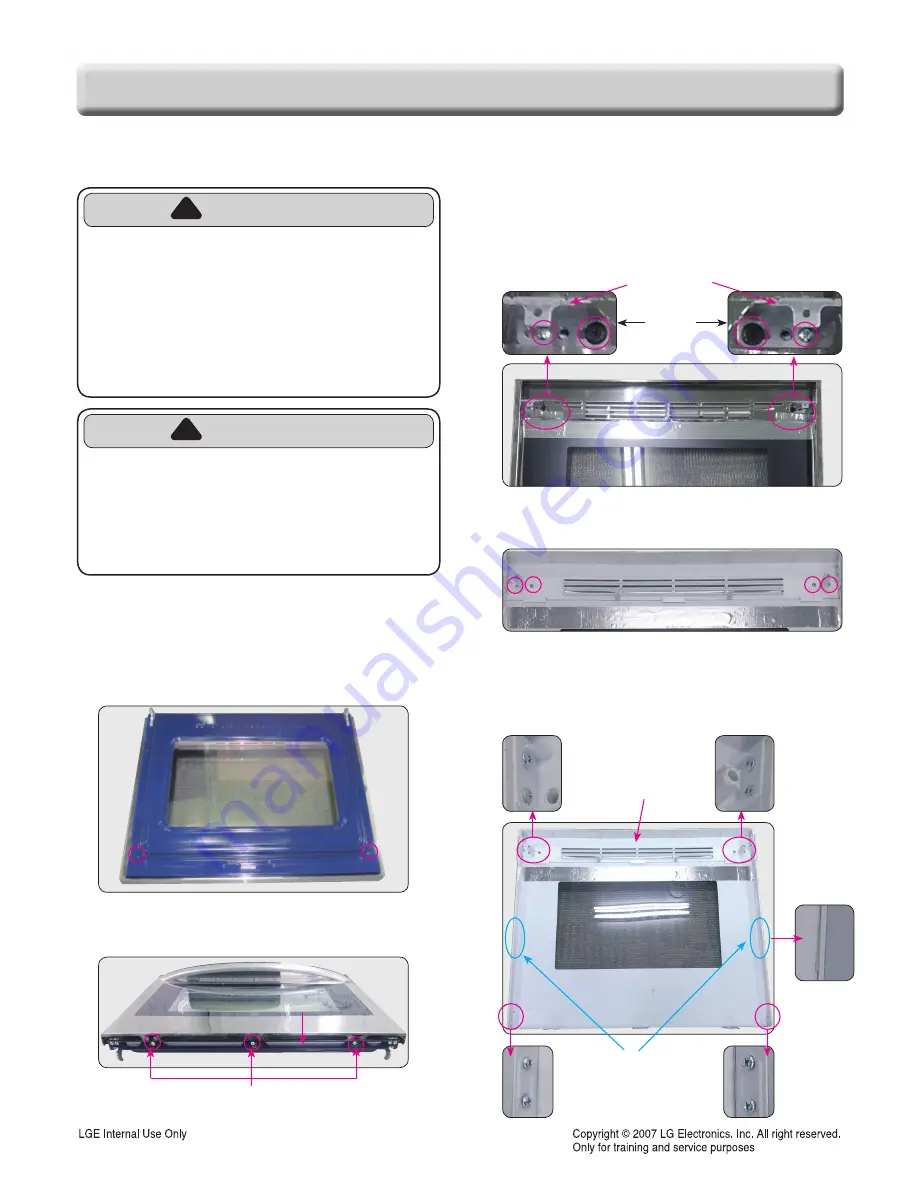
REMOVING THE OVEN DOOR HANDLE
1. Remove the oven door from the range
(See page 3-14 for the procedure).
2. Place the oven door on a padded work surface
with the front glass facing down.
3. Remove 2 screws.
4. Turn the door over. Remove 3 screws from the
door cover assembly and detach the bracket
5. Lift the door cover assembly out and put it down.
6. To remove the door handle for stainless models.
- Remove 4 screws from door bracket and the handle
can be detached from the door cover assembly.
7. To remove the door handle and glass for color models
a) Remove 4 screws and the handle can be detached.
b) Remove 8 screws and detach the glass
supporters and door deco.
Note: There are 2 double sided adhesive tape
on the glass. Be careful when removing
the supporter from glass.
Handle
screws
Door bracket
Door Cover assembly
3 bottom liner screws
Bracket
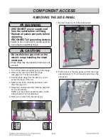
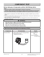
WARNING
• DISCONNECT power supply cord
from the outlet before servicing.
• Replace all panels and parts before
operating.
• RECONNECT all grounding devices.
- Failure to do so can result in severe personal
injury, death or electrical shock.
!
!
CAUTION
• Be careful when you work on the
electric range handling the sheet
metal part.
- Sharp edge may be present and you can cut
yourself.
!
!
Door deco
Double sided
adhesive tape
Summary of Contents for LRE3194BD
Page 39: ...5 2 Composition of control Key Matrix ...
Page 42: ...5 5 Composition of control Cook top display PCB Key Pad ...
Page 71: ...12 3 BAKE COOK WARM PROOF CONV BAKE CONV ROAST SELF CLEANING CR Warming Zone ...
Page 72: ...12 4 RR Cook top Element LR Cook top Element LF Cook top Element RF Cook top Element ...
Page 75: ... EV CONTROLLER PARTS 2381 2031 2050 2006 2048 2037 2042 2036 3006 2034 2041 2075 ...
Page 76: ... EV COOKTOP PARTS 3057 3014 3056 3302 3301 3303 3303 3401 3022 3204 3401 3204 3204 3204 ...
Page 79: ......


