background image

Oven does not  heat, F9

Is the disconnect or loose  

connector?

1.  Between Main PCB and  

Relay PCB (CN17)

2. Electric wiring of relay  

PCB All taps.

3.Electric wiring of electric element

Yes Reconnect or 

repair the 

connector

1

CN17

CN17

Broil

Bake

All taps.

Unplugged the unit

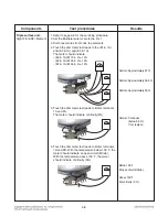
Is the heater normal?

Measure the resistance 

of each heater.

(The resistance is shown 

below)

No

No

Replace the

Failed heater

2

Broil.

Bake

yes

9-5

CHECKING FLOW CHART BY FAILURE

Summary of Contents for LRE3194BD

Page 1: ...tanding Electric Range SERVICE MANUAL MODEL LRE3194ST LRE3194BD LRE3194BM CAUTION BEFORE SERVICING THE UNIT READ THE SAFETY PRECAUTIONS IN THIS MANUAL P NO MFL37118393 June 2018 Printed in Korea Internal Use Only ...

Page 2: ...our dealer If the power cord is defective it must be replaced by a qualified service agent with a UL listed range cord Electrical leads and cables should not be allowed to touch the oven Rating plate is located on the left side of warming drawer The power supply of the appliance should be turned off when it is being repaired FORWARD LG Electronics assumes no responsibility for any repairs made on ...

Page 3: ...ed Bake Delayed timed Bake Broil Favorites Warm Oven lockout Changing hour mode on clock 12HR 24HR Self Clean Easy Clean COMPONENT ACCESS 3 1 3 18 Component Locations 3 1 Removing The Lamp Controller Back Cover and Controller Assembly Membrane Pcb Support 3 2 3 4 Removing Pcbs Main Pcb and Relay Pcb 3 5 Removing the Surface Element and the Ceramic Glass Cooktop 3 6 Removing the Door Latch and the ...

Page 4: ... Main PCB 5 5 Oven Relay PCB 5 5 Cook top display PCB 5 6 Key Pad 5 6 CHECK THE FAILURE CODE 6 1 FAILURE CODE SUMMARY 7 1 BASIC CHECK SUMMARY 8 1 8 2 CHECKING FLOW CHART BY FAILURE 9 1 9 19 Power Failed Dead No display 9 1 9 3 No heating F9 9 4 9 6 Cook top No heating 9 7 9 9 Door Lock System Failure F10 9 10 9 12 Sensing Fail F1 F2 9 13 9 14 Oven hot F6 9 15 9 17 Keypad Failure F3 error 9 18 9 19...

Page 5: ... so can result in severe personal injury death or electrical shock DO NOT touch heating elements or interior surfaces of oven Heating element may be hot even though they are dark in color Interior surfaces of an oven become hot enough to cause burns During and after use do not touch or let clothing or other flammable materials contact heating elements or interior surfaces of oven until they have h...

Page 6: ...T touch heating elements or interior surfaces of oven Heating element may be hot even though they are dark in color Interior surfaces of an oven become hot enough to cause burns During and after use do not touch or let clothing or other flammable materials contact heating elements or interior surfaces of oven until they have had sufficient time to cool Other surfaces of the appliance may become ho...

Page 7: ...rn off or disconnect appliance from power supply and have serviced by a qualified technician VENTILATING HOODS Clean Ventilating Hoods Frequently Grease should not be allowed to accumulate on hood or filter When flaming foods under the hood turn the fan on OVEN Use Care When Opening Door Let hot air or steam escape before you remove or replace food in the oven Do Not Heat Unopened Food Containers ...

Page 8: ...1 4 GENERAL The Model Serial Number label and Tech Sheet locations are shown below Model Serial Number Location MODEL SERIAL NUMBER LABEL AND TECH SHEET LOCATIONS Tech Sheet Location On Rear Cover ...

Page 9: ...W x H x D Exterior Width Exterior Height Exterior Depth Net weight Lbs Kg Rating 30 Freestanding STS Keypad Membrane Keypad Membrane Scroll VFD Yes Yes Yes Option 6 categories 1 Convection auto conversion 0n 0ff 2 Thermostat Adjustment 3 Language English Spanish French 4 Preheating alarm light On Off 5 Beeper Volume normal mute 6 Temperature unit F C Ceramic glass 5 6 1 200 6 1 200 warming zone Du...

Page 10: ...are normally broiled All foods should be turned at least once except fish which does not need to be turned Convection Bake Roast Mode Upper element lower element Rear element some model and fan operate during convection bake Convection bake should be used for cooking casseroles and roasting meats Oven should be preheated for best results when using convection bake Pans do not need to be staggered ...

Page 11: ...lect a warm environment useful for rising yeast leavened products 10 FAVORITES PAD Press to set favorite cooking 11 CLOCK PAD Press before setting the time of day 12 COOK TIME PAD Press and then use the number pads to set the amount of time you want your food to cook The oven will shut off when the cooking time has run out 13 START TIME PAD Use along with BAKE CONV BAKE CONV ROAST COOK TIME and SE...

Page 12: ...R OFF and ON OFF pad 1 Touch START pad to start oven 2 Touch CLEAR OFF pad to cancel a program during cooking or Erase during programming 3 Touch ON OFF pad to start or cancel the surface unit 3 TO TURN ON OFF THE OVEN LIGHT The oven light automatically turns ON when the door is opened The oven light may also be manually turned ON or OFF by pressing the OVEN LIGHT pad Note The oven light cannot be...

Page 13: ...6 BAKE Timed BAKE Delayed timed BAKE This feature can also be used with the CONVECTION BAKE and CONVECTION ROAST modes 7 BROIL 8 FAVORITES 9 WARM 10 OVEN LOCKOUT 11 CHANGING HOUR MODE ON CLOCK 12HR 24HR 12 SELF CLEAN 13 Easy Clean 2 4 USING YOUR RANGE START FAVORITES Once Bread Twice Meat 3 times Chicken START SELF CLEAN Once 4 hour Twice 5 hour 3 times 3 hour START WARM Press and hold the START p...

Page 14: ...de the range The components and their locations are shown below COMPONENT LOCATIONS Oven Light Door Switch Surface Elements Door Locking Motor Micro Switch Main PCB Hinge Hanger Oven Sensor Door Latch Assembly Convection Motor Oven Relay PCB Bake Heater Broil Heater Cook Top Display PCB ...

Page 15: ...e rear panel 3 Remove 2 screws from the lamp cover and remove the lamp cover 4 Remove 12 screws from the controller cover and remove the controller cover 5 Remove the 4 screws from the back cover and remove the back cover REMOVING THE LAMP CONTROLLER BACK COVER AND CONTROLLER ASSEMBLY MEMBRANE PCB SUPPORT WARNING DISCONNECT power supply cord from the outlet before servicing Replace all panels and ...

Page 16: ...side panel 10 Remove 4 screws from the controller assembly back guard R L 11 Remove 6 screws from the controller assembly 12 For serving the KEY Membrane the controller sub assembly should be separated in whole Both Control panel and KEY Membrane are 1 service part COMPONENT ACCESS ...

Page 17: ... proper PCB in default mode and check Main PCB NOTE Refer to the page 5 1 5 6 for composition of control board Main PCB Relay PCB WARNING DISCONNECT power supply cord from the outlet before servicing Replace all panels and parts before operating RECONNECT all grounding devices Failure to do so can result in severe personal injury death or electrical shock CAUTION Be careful when you work on the el...

Page 18: ...NING DISCONNECT power supply cord from the outlet before servicing Replace all panels and parts before operating RECONNECT all grounding devices Failure to do so can result in severe personal injury death or electrical shock 3 Screws Step 6 To remove the surface elements a Remove the wires from the element and limiter terminals b Remove the element brackets for the element you are servicing and th...

Page 19: ...the page 3 6 for the procedure b Remove 3 screws from a cooktop barrier c Remove wiring from the door switch d Remove the door switch from the range To do this squeeze tab on the switch and push the switch in front 2 Screws An actuating rod Unhook the actuating rod Push WARNING DISCONNECT power supply cord from the outlet before servicing Replace all panels and parts before operating RECONNECT all...

Page 20: ...only fasten broil heater s rear bracket but also a thermistor While servicing broil elements the thermistor also should be disassembled 2 upper bracket screws 2 front bracket screws 3 terminals Broil heater thermistor WARNING DISCONNECT power supply cord from the outlet before servicing Replace all panels and parts before operating RECONNECT all grounding devices Failure to do so can result in sev...

Page 21: ... back cover See the page 3 2 4 Remove 4 screws and a powercord 5 Remove 4 screws and detach the bake heater cover from the range Disconnect 2 wiring 2 bake heater receptacles 6 Bend a insulation ceramic wool up and bend 2 flanges up 7 Carefully pull the hidden bake element out of the range REMOVING THE HIDDEN BAKE ELEMENT Bake Heater Cover Insulation ceramic wool 2 flanges ...

Page 22: ...ing clockwise The fan blade can be replaced from inside oven 6 To remove the fan motor assembly a Remove lamp controller and back cover See the page 3 2 b Remove 3 screws from the fan motor bracket and disconnect 2 wiring connections c Pull the fan motor out of the rear panel and the motor can be detached Removing the Convection Fan blade and Fan motor Nut Washer Fan Cover Screw 4ea Conv heater Sc...

Page 23: ...ve the socket from the front of the oven you will have to push the socket out from the back of the unit 6 Disconnect the wires from the socket terminals Glass cover Bulb Socket Clips CAUTION Be careful not to scratch or chip the oven liner paint when you remove the oven light socket in the next step WARNING DISCONNECT power supply cord from the outlet before servicing Replace all panels and parts ...

Page 24: ...ard chip operates the motor 2 The cam moves the door hook connected to latch rod from unlocked position to locked position from locked Position to unlocked position 3 The cam activates the micro switch that causes the motor to stop 4 The locked status remains until the range temperature drops to approximately 500F after end of the self clean or lock out feature is reactivated The motor operates to...

Page 25: ...nsor forward in order to access a connector and disconnect the wirings WARNING DISCONNECT power supply cord from the outlet before servicing Replace all panels and parts before operating RECONNECT all grounding devices Failure to do so can result in severe personal injury death or electrical shock CAUTION Be careful when you work on the electric range handling the sheet metal part Sharp edge may b...

Page 26: ...door To remove the door Step 1 Fully open the door Step 2 Pull the hinge locks down toward Fig 1 the door frame to the unlocked position Step 3 Firmly grasp both sides of the door at the top Step 4 Close door to the door removal position which is approximately 5 degrees refer to the Fig 2 Step 5 Lift door up and out until the hinge arm is clear of the slot Slot Hinge lock Lock Unlock Hinge arm Ind...

Page 27: ...dle and glass for color models a Remove 4 screws and the handle can be detached b Remove 8 screws and detach the glass supporters and door deco Note There are 2 double sided adhesive tape on the glass Be careful when removing the supporter from glass Handle screws Door bracket Door Cover assembly 3 bottom liner screws Bracket WARNING DISCONNECT power supply cord from the outlet before servicing Re...

Page 28: ... from the range See the page 3 14 for the procedure 2 Place the oven door on a padded work surface with the front glass facing down 3 Remove 4 screws 4 Turn the door over Remove 3 screws from the door cover assembly and detach the bracket 5 Lift the door cover assembly out and put it down WARNING DISCONNECT power supply cord from the outlet before servicing Replace all panels and parts before oper...

Page 29: ...liner holes and that the ends of the gasket are pushed fully into their holes Use the pointed end of a pencil to push the gasket ends into the holes Door gasket Gasket clip Liner Hole WARNING DISCONNECT power supply cord from the outlet before servicing Replace all panels and parts before operating RECONNECT all grounding devices Failure to do so can result in severe personal injury death or elect...

Page 30: ...move the lamp controller and back cover See the page 3 2 5 Raise the cooktop assembly See the page 3 6 For the procedure NOTE put the cooktop assembly down on the side panel which is not detached 6 Remove 4 screws from the side panel WARNING DISCONNECT power supply cord from the outlet before servicing Replace all panels and parts before operating RECONNECT all grounding devices Failure to do so c...

Page 31: ...o connectors far enough 3 Resistance checks must be made with power cord unplugged from outlet and with wiring harness or connectors disconnected Before testing any of components perform the following checks WARNING Disconnect power supply cord from the outlet before servicing Replace all panels and parts before operating Reconnect all grounding devices after servicing Failure to do so can result ...

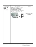
Page 32: ...eplace Components Test procedures Results Normal Infinite Normal Approximately 2 6 kΩ 10 If not replace Abnormal Infinite open below 5Ω shorted NOTE The Micro switch will be held for 13 seconds during lock or unlock ON position Unlock position OFF position Lock position NOTE Ω Value was tested at room temperature 77F 25 C 1 Remove wire leads 2 Measure resistance after cooling down Normal Approxima...

Page 33: ... x 1 Normal Below 5 Ω If not replace Bake heater 1 Remove wire leads 2 Measure resistance after cooling down Normal Approximately 23Ω Abnomal Infinite opened NOTE Ω Value was tested at room temperature 77F 25 C Be careful the element is sensitive to temperature Broil heater 1 Remove wire leads 2 Measure resistance after cooling down Normal Approximately 13 7Ω Abnomal Infinite opened NOTE Ω Value w...

Page 34: ...d 1A The meter should indicate 46 Ω 10 5 Touch the ohmmeter test leads to limiter terminals 1B and 2B With the temperature below 150 F the meter should indicate an open circuit infinite With the temperature above 150 F the meter should indicate continuity 0Ω Components Test procedures Results Normal Approximately 46 Ω If not replace Below 150 F M open circuit infinite Above 150 F M continuity 0 Ω ...

Page 35: ...he meter should indicate 22 Ω 10 5 Touch the ohmmeter test leads to limiter terminals 1B and 2B With the temperature below 150 F the meter should indicate an open circuit infinite With the temperature above 150 F the meter should indicate continuity 0Ω Components Test procedures Results Normal Approximately 22 Ω If not replace Below 150 F M open circuit infinite Above 150 F M continuity 0 Ω Elemen...

Page 36: ...nd 2A The meter should indicate continuity 0Ω Triple surface unit Right Front RF Element Components Test procedures Results Normal Approximately 67 Ω Normal Approximately 48 5 Ω Normal Approximately 50 Ω Normal Continuity below 0 5 Ω If not replace Below 150 F M open circuit infinite Above 150 F M continuity 0 Ω 4 6 6 Touch the ohmmeter test leads to limiter terminals 1B and 2B With the temperatur...

Page 37: ...erminal Element terminal Element terminal Element terminal Element terminal Element terminal Element terminal Element terminal Element terminal Element terminal Element terminal Element terminal Element terminal Element terminal Element terminal Element terminal Element terminal Element terminal Element terminal Element terminal Element terminal Element terminal Element terminal Element terminal E...

Page 38: ...control Wiring Diagram RADIANT COOK TOP Wattage Ω RR 1200W approx 47Ω approx 47Ω approx 50Ω approx 68 3Ω approx 50Ω LR 1200W LF 1400W Inner approx 41Ω 1800W Outer approx 32Ω LF 1100W Single 2200W Dual 3000W Triple 5 1 ...

Page 39: ...5 2 Composition of control Key Matrix ...

Page 40: ...5 3 Composition of control Main PCB Loc No 2006 Cook top display PCB Loc No 2031 Key Pad Oven Relay PCB Loc No 5070 Front Back Controller assembly ...

Page 41: ...5 4 Composition of control Main PCB Oven Relay PCB CN30 CN22 CN21 CN24 CN11 CN13 CN09 CN17 CN25 CN03 CN26 CN1 CN103 CN102 CN17 CN16 CN101 CN100 ...

Page 42: ...5 5 Composition of control Cook top display PCB Key Pad ...

Page 43: ...tion Check the failure code as follow these steps 1 press the clear Button 2 press the BAKE and BROIL Button at the same time If the oven has some failure the Oven will show the failure Code like FIG 1 If the oven do not has any failure the Oven will show it like FIG 2 NOTE After checking for the F code press the CLEAR key to remove all codes FIG 1 FIG 2 Type of F Code Times of the occurred failur...

Page 44: ...utes on cooking except self cleaning EXCEPT PROOF and WARM Case 1 start temperature does not exceed 130 F and oven temperature is less equal than 150 F and max oven temperature is less equal than start oven temp Case 2 oven temperature is less equal than 100 F over 5 minutes on preheating In case of Door Lock Failure in operating Lock motor 1 Wiring 2 Oven Sensor 1 Wiring 2 Oven Sensor 1 Wiring 2 ...

Page 45: ... Lamp coil s resistance Symptom Oven hot F6 Check All heater relays are open short Symptom no heating F9 Check All heater relays and DLB relay are open Symptom Door lock fail F 10 Check relative part Symptom Sensor error or no heating F1 F2 F9 Check Sensor resistance ...

Page 46: ...Symptom Check Point 1 Power Failure Dead 2 No Display 1 Check Electric Wiring 2 Check the Main PCB Input Voltage with CN01 9 1 CHECKING FLOW CHART BY FAILURE ...

Page 47: ...he voltage 120V Yes No Yes Plug the unit Power Failed Dead No display Check the button beep Touch the Clear button Can hear the beep sound Change the Main PCB No Go to No 4 1 2 Is the connector connected to Main PCB disconnected or disassembled CN1 No Unplugged the unit Yes Reconnect or repair the connector 3 CN1 CN1 ...

Page 48: ...d CN01 s connection Normal continuity Abnormal infinite Code L1 to Pin1 of CN01 RD Code N to Pin3 of CN01 WH Yes No Replace the defective harness L1 L1 RD color is L1 White color is N L2 GND N N 4 Normal Abnormal Replace the Main PCB 9 3 CHECKING FLOW CHART BY FAILURE ...

Page 49: ...9 4 CHECKING FLOW CHART BY FAILURE Symptom Check Point 1 No heating 2 F9 1 Check Electric Wiring 2 Check Heater s Resistance 3 Check the Sensor Heater Resistance CHECK CHECK Sensor Resistance Main PCB ...

Page 50: ... relay PCB All taps 3 Electric wiring of electric element Yes Reconnect or repair the connector 1 CN17 CN17 Broil Bake All taps Unplugged the unit Is the heater normal Measure the resistance of each heater The resistance is shown below No No Replace the Failed heater 2 Broil Bake yes 9 5 CHECKING FLOW CHART BY FAILURE ...

Page 51: ...eft digits 4 press the NUM 3 button Normal Themistor value at room temp is from 70 F to 90 F as the above figure Yes Go to No 6 4 No Range Of the resistance Plug the unit Is the resistance of thermistor normal Check Pins 1and 2 of CN13 wiring in main PCB Normal approximately 1 09kΩ at 25 C No Replace the failed thermistor 5 Yes Unplugged the unit CN13 6 Replace the Relay PCB If it doesn t work eve...

Page 52: ...Symptom Check Point 1 Cook top No heating 1 Check Electric Wiring 2 Check the Resistance of each Heater 9 7 CHECKING FLOW CHART BY FAILURE ...

Page 53: ...ector disconnected loose 1 Electric wiring of Main PCB All taps No Reconnect or adjust the connection 1 Unplugged the unit All Taps Measure the resistance of each heater The resistance is shown below No Replace the defected heater 2 Right rear Left rear yes Warm zone ...

Page 54: ...sistance Right Front Outer yes Replace the Main PCB 9 9 CHECKING FLOW CHART BY FAILURE Heater Resistance Ω Approximately Center Rear 47 Center Rear 47 LF 1400W Inner 1800W Outer 47 32 RF 1100W Single 2200W Dual 3000W Triple 50 50 68 3 Center Rear 570 ...

Page 55: ...ART BY FAILURE Symptom Check Point 1 Door Lock System Failure 2 F10 1 Check the Electric wiring 2 Check the Motor s Resistance 3 Check the Relay PCB Door Lock Relay Door lock Relay Door lock switch signal Door switch signal ...

Page 56: ...isconnect or loose connector 1 Between Main PCB and Relay PCB CN17 2 Electric wiring CN100 of relay PCB 3 Electric wiring of Locking Motor and Micro Switch 4 Electric wiring of CN13 of Main PCB Yes Reconnect or adjust the connection 2 CN100 CN13 Unplugged the unit No Check the operation of door lock motor Press Start button for 3 seconds and try open the door Is the door open Yes Go to No 2 1 Plug...

Page 57: ...ormal measure the resistance of door lock switch T normally open type No Replace the micro switch 3 Yes Normal Abnormal Is the resistance of the locking motor normal measure the resistance of locking motor Normal approximately 2 6kΩ Abnormal infinite or below 5 Ω No Replace the locking motor 4 Yes ...

Page 58: ...Symptom Check Point 1 Sensing Fail 2 F1 3 F2 1 Check the Electric Wiring 2 Check the Test Mode 3 Check the Sensor s Resistance 9 13 CHECKING FLOW CHART BY FAILURE ...

Page 59: ... PCB Normal approximately 1 09kΩ at 25 C No Replace the failed thermistor 2 CN13 Is the value of thermistor normal Check with the test mode To enter the test mode follow these steps 1 press the clear button 2 press the BAKE BROIL button at the same time 3 press the BAKE BROIL button at the same time again Software version is displayed at the left digits 4 press the NUM 3 button Normal Themistor va...

Page 60: ...Symptom Check Point 1 Oven hot 2 F6 1 Check the Resistance of the Relay 9 15 CHECKING FLOW CHART BY FAILURE Relay Short check ...

Page 61: ...gged the unit Yes Is the Heater relay normal Measure the resistance of heater relay and L Normal infinite Abnormal continuity No Replace the relay PCB 2 Yes Yes Is the DLB relay normal Measure the resistance Normal infinite Abnormal continuity No Replace the relay PCB 3 Normal Abnormal Normal Abnormal Broil RY105 Relay Resistance CN101 1st pin and 2nd pin Bake RY104 Relay Resistance L2 DLB1 RY106 ...

Page 62: ...utton 2 press the BAKE BROIL button at the same time 3 press the BAKE BROIL button at the same time again Software version is displayed at the left digits 4 press the NUM 3 button Normal Themistor value at room temp is from 70 F to 90 F as the above figure No Replace the Main PCB 4 Plug the unit 9 17 CHECKING FLOW CHART BY FAILURE ...

Page 63: ...9 18 CHECKING FLOW CHART BY FAILURE Symptom Check Point 1 Keypad Failure 2 F3 Error 1 Check the Door Locking System 2 Check the Electric Wiring ...

Page 64: ...utton operation using key test mode To enter the test mode follow these steps 1 press the clear button 2 press the BAKE BROIL button at the same time 3 press the BAKE BROIL button at the same time again Software version is displayed at the left digits 4 press the NUM 7 button 5 Check the button Refer to the next page appendix 2 3 Plug the unit If button is not operated Replace the Main PCB 9 19 CH...

Page 65: ...ve sequence and check the beep sound when key is accessed 2 If change the key access order the buzzer make double beep sound 3 The buzzer has no operation when key accessed it would be defected How to stop Key Test mode Press 1st 2nd 27th CLEAR Press CLEAR button one more Key operation Test ...

Page 66: ...e 9 1 9 3 Verify power is present at unit Verify that the circuit breaker is not tripped Replace household fuse capacity Check circuit breaker Repair or replace wiring see wiring diagrams Test and or replace element Test and or replace PCB Verify all connections are clean and tight replace broken wires Test and or replace main PCB Test and or replace element Line voltage should be minimum 240 volt...

Page 67: ... period after self clean cycle not complete Improper use of oven e g being used to heat the home Worn or broken broil stop roller Replace main PCB Replace main PCB Verify power is present at unit Verify that the circuit breaker is not tripped Replace household fuse but do not fuse capacity Refer to Owner s manual instructions Verity all connections are clean and tight replace broken wire Test and ...

Page 68: ...nsor needs to be adjusted Adjust hinges or replace hinges Adjust or replace hinges Adjust hinges outward Do not cover racks with foil Install tempered glass toward the heat Do not use harsh abrasives or scouring pads See Owner s manual intructions Apply a small amount of vegetable oil to a paper towel and wipe the edges of the oven racks with the paper towel Do not spray with pam or other lubrican...

Page 69: ...12 1 SCHEMATIC DIAGRAM NOTE Schematic diagram shows door switch In the cook position with the oven door open and elements off WARNING POWER MUST BE DISCONNECTED BEFORE SERVICING THE APPLIANCE ...

Page 70: ... oven circuit 1 Check the line voltage household fuse or circuit breaker 2 Check for loose wiring or mis wiring within electric range NOTE The following individual circuits are for use in diagnosis and are shown in the ON position OVEN LIGHT CLOCK DISPLAY ON BROIL EASY CLEAN ...

Page 71: ...12 3 BAKE COOK WARM PROOF CONV BAKE CONV ROAST SELF CLEANING CR Warming Zone ...

Page 72: ...12 4 RR Cook top Element LR Cook top Element LF Cook top Element RF Cook top Element ...

Page 73: ...TOP PARTS CONTROLLER PARTS CAVITY PARTS MODEL Customer Model Product Code SVC Model MODEL Customer Model Product Code SVC Model MODEL Customer Model Product Code SVC Model MODEL Customer Model Product Code SVC Model Customer Model MODEL Product Code SVC Model ...

Page 74: ...DOOR PARTS 1023 1801 1733 1000 W225 1734 1704 1703 1028 1020 W222 1009 1735 1021 1024 1024 1026 W225 W222 W101 W101 1703 1045 W222 W222 EV ...

Page 75: ... EV CONTROLLER PARTS 2381 2031 2050 2006 2048 2037 2042 2036 3006 2034 2041 2075 ...

Page 76: ... EV COOKTOP PARTS 3057 3014 3056 3302 3301 3303 3303 3401 3022 3204 3401 3204 3204 3204 ...

Page 77: ... EV DRAWER PARTS 8517 8524 8512 8602 8520 8501 8504 8508 8514 W228 8513 8513 8388 5505 851D 851D 5505 8502 8507 ...

Page 78: ...230 5506 5513 5951 W233 W232 5407 5700 5063 5505 5505 W230 W225 W225 5516 5512 5512 5515 5132 5032 5401 5410 5517 5037 5509 5502 5016 5067 3093 3109 5510 5070 5409 5508 3063 3013 5539 5012 5503 W301 8511 W229 9381 5511 5532 5533 5514 5521 5507 W301 5507 CAVITY PARTS ...

Page 79: ......

Reviews: