9-14
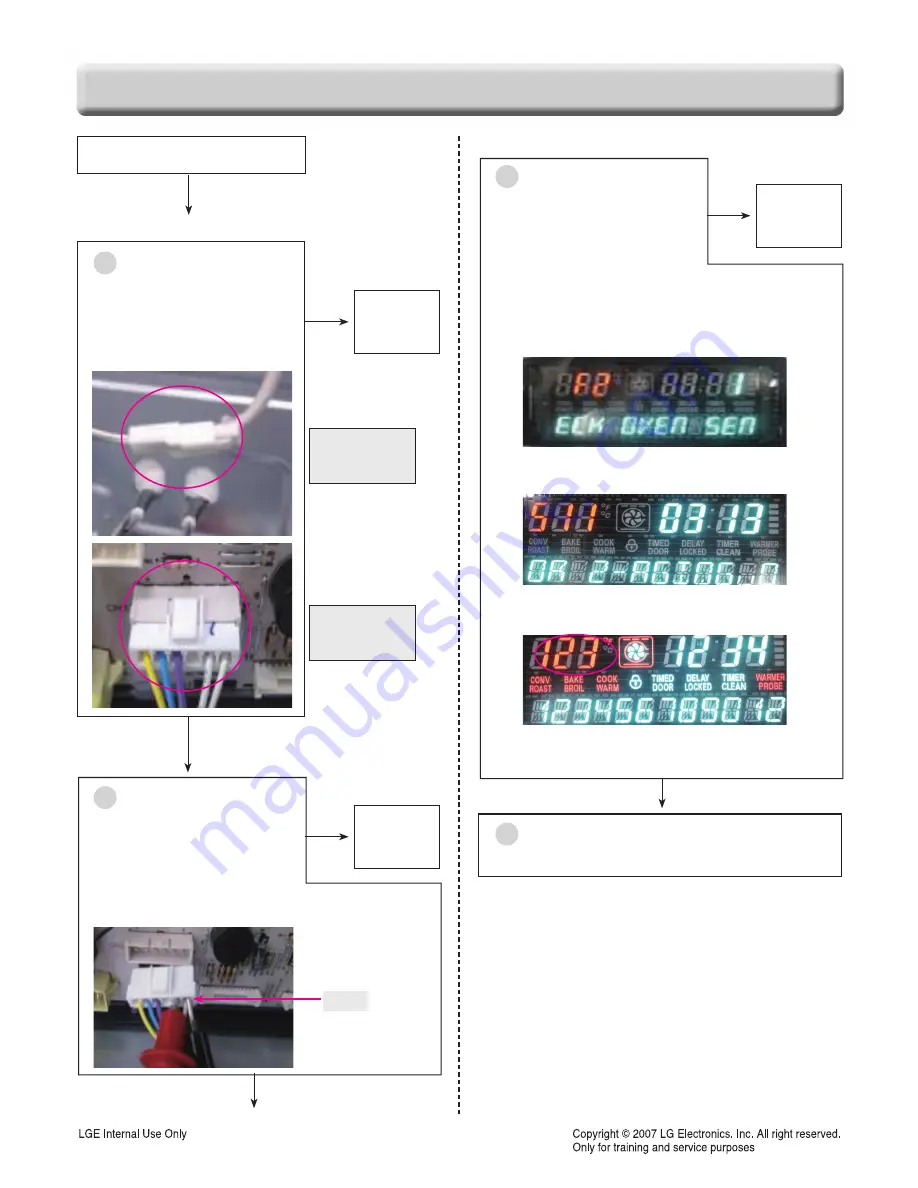
CHECKING FLOW CHART BY FAILURE
Is the Connector
disconnected or loose?
1. Sensor connection
2. CN13 of Main PCB
No
Yes
Unplugged the unit
Sensing Fail, F1, F2?
Yes
Reconnect
or adjust the
connection
1
Sensor
connection
CN13
connection
Is the resistance of
thermistor normal?
Check:
Pins 1and 2 of CN13 wiring in main PCB
Normal- approximately 1.09kΩ at 25˚C
No
Replace the
failed
thermistor
2
CN13
Is the value of thermistor
normal?
Check with the test mode
To enter the test mode, follow these steps:
1. press the “clear” button
2. press the “BAKE”, “BROIL” button
at the same time
3. press the “BAKE”, “BROIL” button
at the same time again.
Software version is displayed at the left digits
4. press the NUM “3” button
Normal : Themistor value at room temp is from 70˚F
to 90
˚F
as the above figure.
Yes
Go to No 1
3
4
Plug the unit
Replace the Main PCB.
No
Summary of Contents for LRE3194BD
Page 39: ...5 2 Composition of control Key Matrix ...
Page 42: ...5 5 Composition of control Cook top display PCB Key Pad ...
Page 71: ...12 3 BAKE COOK WARM PROOF CONV BAKE CONV ROAST SELF CLEANING CR Warming Zone ...
Page 72: ...12 4 RR Cook top Element LR Cook top Element LF Cook top Element RF Cook top Element ...
Page 75: ... EV CONTROLLER PARTS 2381 2031 2050 2006 2048 2037 2042 2036 3006 2034 2041 2075 ...
Page 76: ... EV COOKTOP PARTS 3057 3014 3056 3302 3301 3303 3303 3401 3022 3204 3401 3204 3204 3204 ...
Page 79: ......


