background image


GAS RANGE 

Page 61 of 72 

TRAINING MANUAL 


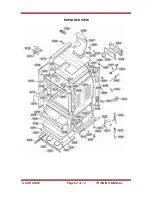
EXPLODED VIEW 


Summary of Contents for LRG30855S Series

Page 1: ...LG TRAINING MANUAL LRG30855Sx Gas Range Fall 2007 LG TRAINING MANUAL ...

Page 2: ...pliance Alternatively you can touch your finger repeatedly to a ground connection point or unpainted metal in the appliance Before removing a replacement part from its package touch the anti static bag to a ground connection point or unpainted metal in the appliance Handle the electronic control assembly by its edges only When repackaging a failed electronic control assembly in an anti static bag ...

Page 3: ...Timer 12 Probe 13 Warming Drawer 13 Self Cleaning Cycle 14 Component Location Views 15 Oven Door Removal and Replacement 18 Warming Drawer Removal and Replacement 19 Warming Drawer Element and Gasket 19 Gas Shutoff Valve 20 Main Top Removal 21 Side Panel Removal 21 Oven Hinge Removal 22 Door 23 Oven Light and Switch 24 Oven Burner Ignition 25 Broil Burner and ignitor 26 Bake Burner and Ignitor 27 ...

Page 4: ...Gas vs Propane or LP 43 Convert The Surface Orifices Spuds 43 Convert The Bake and Broil Orifices 45 Check the Flame Quality 45 Oven Calibration 46 Lock Motor and Latch Circuit 47 Clean And Lock Sequence 48 Service Test Mode 49 Test Mode Chart 50 Failure Codes F Codes 51 Key Panel Test 52 Warming Drawer Performance 52 Oven Self Clean Operation 52 Convection Fan Operation 52 Parts List 53 Exploded ...

Page 5: ... Gas natural gas or propane is explosive If you smell gas Do not try to light any appliance Do not touch or operate any electrical switch Do not use any phone wired portable or cellular in the building Immediately call the gas supplier from a neighbor s phone Follow the gas supplier s instructions If you can not contact the gas supplier call the fire department To avoid personal injury disconnect ...

Page 6: ...e above the warming drawer This plate also shows the burner ratings fuel type and pressure settings from the factory The mini manual is in an envelope taped behind the back panel The propane LP Gas instructions are attached to the back of the range Inside near the gas valve is a set of LP orifices for the conversion We recommend re using this bracket to save the natural gas orifices in the event t...

Page 7: ...GAS RANGE Page 6 of 72 TRAINING MANUAL WARRANTY ...

Page 8: ...resistance 250 KW Min GAS SUPPLY This range is designed to operate at a pressure of 5 inches of water column on natural gas or 10 inches on LP propane or butane MINIMUM CLEARANCES This drawing shows the minimum clearances for the gas range The 30 requirement between stovetop and cabinet bottom allows sufficient space to the installation of a standard over the range microwave oven This drawing show...

Page 9: ...the range is pushed back into place the bracket attached to the range will be positioned under the wall bracket and it will keep the range from tipping TOOLS For the most part ordinary hand tools are sufficient for installing the range It will be necessary to check the incoming gas pressure and to regulate it if it is out of specification A manometer is essential for proper regulation of gas press...

Page 10: ...inguish the flame When one burner control is in the IGNITE position the igniters on all the surface elements will fire The surface burners are controlled by manual valves These valves have a low flame or simmer adjustment which will be covered later in this manual OVEN VENT The oven is vented through ducts at the rear of the range top Do not block these vents while cooking in the oven Because of t...

Page 11: ...on the warming drawer 8 SELF CLEAN Press to start a self cleaning cycle 9 CONV BAKE Press to select convection baking 10 CONV ROAST Press to select convection roasting 11 CLOCK Press then use the number pads to set the time 12 TIMER ON OFF Press to use the timer feature 13 OVEN LIGHT Turns the oven light ON or OFF 14 CLEAR OFF Press to cancel any oven setting It does not affect the warming drawer ...

Page 12: ...play will show the changing temperature When the set point is reached the buzzer will sound 4 Touch CLEAR OFF when cooking is complete OVEN BROILING This oven is not designed for open door cooking To operate the oven for regular broiling 1 Place the meat or fish on the broiler grid in the broiler pan 2 Follow the suggestions for shelf positions in the Broiling Guide owner s manual page 15 3 The ov...

Page 13: ...lay will show the changing temperature When the set point is reached the buzzer will sound 4 To change the oven temperature touch CONV BAKE or CONV ROAST and then touch the number pads to set the new desired temperature 5 Touch CLEAR OFF when broiling is complete AUTO RECIPE CONVERSION When using the convection oven it will automatically convert the temperatures from regular baking to convection b...

Page 14: ... touch CLEAR OFF If the probe is removed from the food before the setpoint is reached the buzzer sounds and the display flashes until the probe is removed from the socket You can use the timer even though you cannot use timed oven functions while using the probe To avoid damaging the probe be certain the food is defrosted before inserting the probe It should not touch bone fat or gristle When remo...

Page 15: ...ser like SoftScrub Rinse well and dry thoroughly Do not attempt to clean the gasket The fiberglass material cannot withstand abrasion It is essential for the gasket to remain intact If you detect fraying or wear have the gasket replaced To set the oven for self cleaning 1 Touch SELF CLEAN 2 Use the number pads to set a clean time or go with the default of 420 four hours and twenty minutes 3 Touch ...

Page 16: ...GAS RANGE Page 15 of 72 TRAINING MANUAL COMPONENT LOCATION VIEWS ...

Page 17: ...GAS RANGE Page 16 of 72 TRAINING MANUAL COMPONENT LOCATION VIEWS ...

Page 18: ...GAS RANGE Page 17 of 72 TRAINING MANUAL COMPONENT LOCATION VIEWS Control panel in service position Cooktop removed with heat shield and latch assembly cover removed ...

Page 19: ... position Lift the door and pull it straight up OVEN DOOR REPLACEMENT Hold the door by the top corners in a nearly vertical position similar to removal in the previous step Guide the hinge arms into the door slots and push the door onto the arms firmly Close the door and check for alignment Operate the door a couple of times to make sure it opens and closed properly and without binding If the door...

Page 20: ...of the track and pull the slide out Lift the track slightly and twist it toward the center of the range to disengage the front tab Then pull the track forward to release it WARMING DRAWER ELEMENT Reminder Unplug the range before servicing the element You ll need to remove the warming drawer to service the heating element Remove the two T 15 Torx screws that hold the terminal cover The element is a...

Page 21: ...lve shuts off the gas to the oven ONLY and has no effect on the surface burners This shutoff valve is accessible from the inside of the range after the warming drawer is removed The shutoff valve allows servicing the oven burners without having to pull the range out and shut off the gas main ...

Page 22: ...NEL REMOVAL 1 Remove the range from its installation 2 Remove the door Page 18 3 Remove the warming drawer Page 19 4 Remove the main top Page 21 above 5 Remove six Phillips screws from the top of the side panel 6 Remove the Phillips screw from the front panel under the hinge 7 Remove four hex head screws from the back edge of the side panel 8 Slide a putty knife into the side panel under the manif...

Page 23: ...move the side panel Page 21 5 Note the position of the hinge spring and the paint indicator Remove the hinge spring 6 Remove the E clips from the hinge pin and remove the pin 7 Remove the two hex head screws that attach the hinge to the frame 8 Position the top of the hinge body into the notch in the hinge arm see photo and rotate the hinge body clockwise to remove ...

Page 24: ...ter sections of the inner door panel 1 Remove the oven door Page 18 2 Place the door inside up on a padded surface 3 Remove the two Torx T 20 screws from the top corners of the inner panel Remove the four hex head screws from the bottom of the door and remove the inner assembly 4 Place the inner assembly inside up on a padded surface 5 Remove the four hex head screws the inner door panel and the i...

Page 25: ...check for 120 VAC across the terminals If 0 volts check the door switch and wiring 1 Unplug the oven 2 Push the wire clip to the side and remove the glass cover 3 Remove and replace the bulb 4 Clean the glass cover using a wet cloth Be sure the cover is completely cool OVEN DOOR SWITCH The switch is on the left side of the door frame and is accessible from the front 1 Unplug the oven 2 Pull the sw...

Page 26: ... should provide a steady current flow of 3 3 to 3 6 amps 3 03 to 3 30 VAC in the circuit which keeps the gas valve open If the ignitor ages and its resistance increases significantly the current flow will decrease respectively and the gas valve will no longer open If the ignitor glows red but does not draw a minimum of 2 9 amps the failure is usually with the ignitor rather than the valve ALWAYS c...

Page 27: ...ed into the burner inlet opening 6 Remove the access cover from the back of the range and disconnect the ignitor connector 7 Remove the wire retainer and gently pull the connector through the oven wall and remove the ignitor IMPORTANT When replacing the ignitor the connector end must be positioned OUTSIDE the range insulation Do not allow the connector to be inside or next to the insulation Allow ...

Page 28: ...e the two hex head screws that hold the ignitor to the bake burner 5 Disconnect the ignitor wires located behind the warming drawer Gently pull the connector through the oven floor and remove the ignitor 6 Remove the hex head screw that holds the front of the burner in place 7 Remove the two hex head screws located behind the warming drawer that hold the burner in place and then remove the burner ...

Page 29: ...BROIL and observe the broil burner flame 6 Allow the oven to cool and reassemble it NOTE The oven door must remain closed when testing the bake and broil flames The window should be clean before starting When testing the bake and broil elements observe the flames for a minimum of two minutes Give the burners time to reach operating temperature The flame should not lift or blow off the burner durin...

Page 30: ...er a digital or water slack tube manometer Measuring gas pressure can be easily accomplished at any of the 5 surface burners Remove a burner grate and one of the sealed burners Then place the gas pressure measuring tube over the orifice With the pressure fitting over the orifice and the range unplugged turn the surface valve to an open position and record the gas pressure If the gas pressure measu...

Page 31: ...arming drawer Page 19 3 Remove the bake burner Page 27 4 Remove the gas line connections at the valve The line by the regulator is 11 16 and the line by the oven shutoff safety valve is 9 16 5 Remove the 5 hex head screws that secure the combi valve 6 Remove the valve The regulator has an adjustment for converting the range from natural gas to propane LP The adjustment screw is marked to show whic...

Page 32: ...emove the nut from the convection fan blade Hold the blade securely and turn the nut clockwise NOTE This nut has a left handed thread 4 Remove the fan blade and washer from the motor shaft 5 Remove the four Phillips screws that attach the motor to the back of the range and remove the motor 6 Disconnect the 3 wire connector from the motor 7 Remove the six Phillips screws that mount the motor frame ...

Page 33: ...er of the oven 1 Remove the two Phillips screws that attach the probe outlet to the oven 2 The outlet and wiring can be pulled out approximately 1 NOTE When replacing the probe outlet cut the wires as close to the end as possible Then splice them to the new outlet using heat resistant connectors ...

Page 34: ... that attach the sensor to the oven wall 5 Gently pull the sensor wire in to the oven cavity NOTE When replacing the sensor use a small flat blade screwdriver to push and guide the sensor wire harness into the oven liner NOTE When replacing the oven temperature sensor the connector end must be positioned OUTSIDE the range insulation The insulation should be allowed to fill around the lead wires to...

Page 35: ...over the grates 3 Grasp and pull the bottom of the control panel out about one inch and lift it off the top rear corner screws 4 Carefully fold the control panel over the grates into the service position NOTE To avoid damage to the porcelain components do not overtighten the screws SPARK MODULE The spark module is in the back guard and held in place by two plastic tabs one on each side Put the con...

Page 36: ...g the ERC 1 Wire tie holding wire harness to ERC 2 Ground wire to ERC board 3 Wiring harness to touch panel CONTROL PANEL AND TOUCH BOARD The control panel and touch board are supplied as an assembly If the touch board is damaged the entire control assembly must be replaced To replace the control panel and touch board put the control panel into service position The ERC must be removed and the wiri...

Page 37: ...let tube not visible see photo above BURNER REMOVAL 1 Remove the maintop See page 21 2 Remove the two hex head screws that attach the shield to the top right side of the manifold panel Omit this step if servicing the left front or left rear burner 3 Pull the ignitor wire out of the wire inlet bracket 4 Use a 5 8 socket and extension to remove the nut that holds the bracket to the inlet tube and li...

Page 38: ...head MAINTOP BURNER FLAME ADJUSTMENTS The top burners do not have air shutters and fixed non adjustable orifices are used If the flames blow off the burner or have yellow tips check the following Gas pressure 5 Natural gas 10 LP gas Inspect orifice to be sure it is drilled on center and free of debris or burrs Be sure the correct size orifice is in the proper location Make sure the range was prope...

Page 39: ...er on LOW Turn the first knob from HI to LOW quickly The third burner should stay lit MANIFOLD PANEL 1 Remove the oven door See page 18 2 Remove the main top See page 21 3 Remove the surface burner valve knobs by pulling each knob straight out 4 Remove the two hex head screws that attach the shield to the top right side of the manifold panel 5 Remove the 2 Phillips head screws and the 2 guides fro...

Page 40: ...e the manifold panel See page 38 3 Using a in open end wrench disconnect the burner inlet tube from the valve 4 Remove the in hex head screw that holds the valve to the manifold 5 Lower the valve from the manifold 6 Remove the protective cover from the valve stem 7 Remove the ignitor switch from the valve See page 40 WARNING Ensure the valve seal and the screw seal are carefully positioned before ...

Page 41: ...or right rear burner valve from the gas manifold Caution The 2 lock tabs on each ignitor switch are fragile Tab breakage can occur if excessive release pressure is applied When replacing the ignitor switch for the left or right rear burner remove the valve from the gas manifold 1 Be sure the range is unplugged 2 Remove the manifold panel See page 39 3 Remove the protective cover from the valve ste...

Page 42: ... of the manifold panel 3 Remove the nut that holds the inlet tube to each valve 4 Using a 13 16 open end or adjustable wrench disconnect the gas inlet tube from the gas manifold 5 Remove the left and right rear burner knobs then remove the four Phillips head screws from the front of the manifold panel 6 Remove the two in hex head screws that attach the gas manifold to the range 7 Remove the five b...

Page 43: ...led by a metal cover To replace the door latch assembly 1 Remove the oven door See page 18 2 Remove the main top See page 21 3 Remove the two hex screws that attach the shield to the top right side of the manifold panel 4 Remove the four hex screws that hold the latch assembly cover in place 5 Remove the cover 6 Mark and disconnect the wiring from the latch assembly 7 Remove the two T 15 Torx scre...

Page 44: ...n the pin 180 degrees and snap the pin back into the cap The hex nut is marked with NG for natural gas and LP for propane There is an arrow showing which way to install the nut The nut pictured at the left is marked to install with the bottom end screwed into the regulator to set it for natural gas If you turn it over you will see the LP marking The long end goes into the regulator to set it for L...

Page 45: ... down over the ring Install the LP orifice spuds into their correct positions as described as follows A mark I II or III is engraved on the top of the orifice to denote the location of the orifice as shown in the illustration The marks appear on both the LP and Natural Gas orifices The locations indicated by the marks are the same for both gasses The LP orifices are color coded as well as marked w...

Page 46: ...t the range must be reverted to natural gas in the future CONVERT THE BAKE and BROIL ORIFICES Remove oven door warming drawer and oven bottom The oven burner orifice hood is located behind the warming drawer The broil burner orifice hood is located on the right upper corner of the oven cavity To convert to LP use a wrench to turn the orifice hoods clockwise until it is snug with the base approxima...

Page 47: ...50 F 177 C when the average center oven temperature is between 350 F and 390 F 177 C and 199 C Customers may change the average center oven temperature by 35 F 2 C to satisfy their own cooking needs To recalibrate the oven Touch the BAKE and BROIL HI LO pads simultaneously and hold for 3 seconds until the display shows SF Touch the BAKE pad A number shows in the display Touch BAKE once to decrease...

Page 48: ...latch switches switch 1 for unlocked or switch 2 for locked back to the ERC If neither switch is closed and the oven temperature is below 450 F 232 C the ERC will energize the lock motor circuit until the correct switch closes to complete the circuit If circuit to the correct switch is open the lock motor will run continuously with the oven below 450 F 232 C The cam on the motor performs two funct...

Page 49: ...g the clean cycle and pressing START pad the control energizes the lock relay Voltage 120 VAC is applied to the lock motor circuit Oven door must be closed before lock motor can run LOCKED will flash and control will beep until the door is closed The lock motor begins to revolve and turns a cam mounted to the motor shaft The word LOCKED will flash on and off on the display while the lock motor is ...

Page 50: ...Unplugging components for testing can damage component connections The range must be powered down unplugged before entering the test mode Test Mode Entry 1 Unplug the range for a minimum of 15 seconds 2 Power up the range all segments in the display and the control panel selections illuminate and wait until the time of day is flashing 3 Touch COOK TIME DELAY START and 8 simultaneously The display ...

Page 51: ... clockwise direction with door shut as long as CONV BAKE key is held SELF CLEAN Hold the SELF CLEAN key This action will energize the Door Motor relay and display the door inputs in select decimal format in the temperature center digit 0 Transition Locked icon blinks 1 Unlocked No icon 2 Locked Locked icon solid WARMING DRAWER Touch WARMING DRAWER SET OFF then hold START The START key will initiat...

Page 52: ... sensor input to control Oven above 615 F with lock input untrue Oven above 915 F with lock input true F3 Open sensor Sensor is 2900 to infinite ohms while in a heating mode F4 Shorted sensor Sensor is 0 to 950 ohms maximum while in a heating mode F6 START key input failure Shorted START key detection F7 Shorted key detection except for slew entry and CLEAR OFF keys Short for approximately 40 seco...

Page 53: ...d the ERC One of three warming drawer heat settings can be selected After a pre determined timed preheat period cycling of the element is controlled by the ERC with a four minute duty cycle Setting Preheat Time On Duty Cycle On Time Duty Cycle Off Time Target Temp 1 LOW 900 seconds 144 seconds 96 seconds 200 F 93 C 2 MED 1 200 seconds 192 seconds 48 seconds 250 F 121 C 3 HIGH 60 seconds Constant O...

Page 54: ...BZ37170506 SCREW 8 32 9 EBZ37169801 BOX BURNER SP 10 EBZ37184501 CKT BRACKET SM 11 EBZ37184502 CKT BRACKET MID 12 EBZ37170001 SW VALVE SERVICE 270 2WI 12 EBZ37170002 SW VALVE SERVICE 270 1WI 13 EBZ37184503 CKT BRACKET LG 14 EBZ37170201 MANIFOLD PIPE 15 EBZ37170601 VALVE BURNER 270 9100 15 EBZ37170603 VALVE BURNER 270 HI CAP 15 EBZ37170604 VALVE BURNER 270 11000 15 EBZ37170605 VALVE BURNER 2700 16 ...

Page 55: ...AD FELT WH 92 EBZ37170514 SCREW GROUND 100 EBZ37191510 END SUPPORT RT 100 EBZ37191511 END SUPPORT LF 104 EBZ37191508 GLASS AND TRIM ASM 105 EBZ37191708 CONTROL GLASS TOUCH 106 EBZ37191502 COVER BACK UPPER 107 EBZ37191503 COVER BACK LOWER 108 EBZ37170516 SCR 8 18 AB HXW 5 8 S 108 EBZ37170517 SCREW CR 108 EBZ37170518 SCR 8 18 AB PHR 1 2 S 108 EBZ37170519 SCR 8 18 AB PHR 1 2 S 110 EBZ37191705 SPARK M...

Page 56: ...6 BURNER LARGE 12000 157 EBZ37192707 VISION BURNER XL 159 EBZ37192708 BURNER MEDIUM 9500 168 EBZ37169813 CLIP ELECTRODE 169 EBZ37169814 VENTURI 15K LP 170 EBZ37170524 SCREW WH 170 EBZ37170525 SCREW WH 171 EBZ37191709 HARNESS INTERFACE 200 EBZ37193001 RACK OVEN 201 EBZ37193002 RACK BROILER PAN 202 EBZ37193003 PAN BROILER 203 EBZ37191707 LINE CORD 204 EBZ37170509 SCREW BLK 204 EBZ37170510 SCREW 8 18...

Page 57: ...403 RING RETAINING 226 EBZ37197404 HOOK DOOR SPRING 227 EBZ37197405 SPRING DOOR 228 EBZ37197501 CLIP WIRE 229 EBZ37198002 HOUSING RECEPTACLE 230 EBZ37198001 PUSH IN RECEPTICLE 231 EBZ37213201 ARM ANTI TIP 232 EBZ37213202 BRACKET ASM ANTI TIP 233 EBZ37198003 SWITCH PLUNGER 235 EBZ37198004 OVEN LAMP 235 EBZ37213207 OVEN LAMP 236 EBZ37213203 SPACER BASE 237 EBZ37171701 TUBE MANIFOLD SUPPLY 238 EBZ372...

Page 58: ...RT RIVET LFT 254 EBZ37197408 SUPPORT RIVET RT 256 EBZ37214101 GASKET VENT 257 EBZ37214102 VENT ASSEMBLY 258 EBZ37214103 BRACE VENT 259 EBZ37197701 SLIDE BEARING ASM RT 259 EBZ37197702 SLIDE BEARING ASM LF 260 EBZ37214104 GASKET OVEN SEAL LG 261 EBZ37214105 INSULATION OVEN WRAP 262 EBZ37214122 INSULATION OVEN BACK 268 EBZ37169810 DEFLECTOR THERMOSTAT 269 EBZ37169803 DEFLECTOR SIDE 270 EBZ37169804 O...

Page 59: ...TOM INNER GUARD 293 EBZ37214119 GUARD BOTTOM MIDDLE 294 EBZ37169808 COVER TERMINALS 295 EBZ37192902 INSULATION VENT 296 EBZ37214120 SHIELD HEAT INNER 299 EBZ37214121 CLIP WIRE 300 EBZ37215101 BODY DRAWER 306 EBZ37215126 PANEL DRAWER 312 EBZ37215103 WASHER CONTOURED 312 EBZ37215113 WASHER CONTOURED 314 EBZ37215127 GLASS DOOR 315 EBZ37215105 LINER ASM WELD DOOR 317 EBZ37215129 VENT TRIM 318 EBZ37215...

Page 60: ... DRAWER 345 EBZ37215122 LINER DRAWER 354 EBZ37215601 SCREW 10 32 MTG HNDL 359 EBZ37215611 TRIM BOTTOM DOOR WH 360 EBZ37215602 SEAL DRAWER 361 EBZ37215603 SCREW 365 EBZ37215614 HANDLE 366 EBZ37215605 SCREW DOOR ASM 4 PER 375 EBZ37215606 PANEL DRAWER SPACER 375 EBZ37215607 BRACKET DOOR 400 EBZ37215608 WINDOW SPACER ASM 461 EBZ37215701 SCREW 700 EBZ37214901 RETAINER INSULATION VENT 703 EBZ37214902 BR...

Page 61: ...GAS RANGE Page 60 of 72 TRAINING MANUAL EXPLODED VIEW ...

Page 62: ...GAS RANGE Page 61 of 72 TRAINING MANUAL EXPLODED VIEW ...

Page 63: ...GAS RANGE Page 62 of 72 TRAINING MANUAL EXPLODED VIEW ...

Page 64: ...GAS RANGE Page 63 of 72 TRAINING MANUAL EXPLODED VIEW ...

Page 65: ...GAS RANGE Page 64 of 72 TRAINING MANUAL INSTALLATION DIMENSIONS ...

Page 66: ...GAS RANGE Page 65 of 72 TRAINING MANUAL SCHEMATICS AND WIRING DIAGRAMS ...

Page 67: ...GAS RANGE Page 66 of 72 TRAINING MANUAL SCHEMATICS AND WIRING DIAGRAMS ...

Page 68: ...NTS 1 Oven light 2 Line 3 Bake 4 Neutral 5 Broil 6 Warming drawer 7 Lock motor 8 Convection Fan High 9 Convection Fan CONNECTOR 2 Pin 1 Probe Pin 2 Ground Pin 3 Unlock Latch switch 1 Pin 4 Lock Latch switch 2 Pin 5 Common Pin 6 VDD Sensor Pin 7 Blank Pin 8 Oven Sensor ...

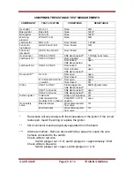
Page 69: ...n Door switch N to blue wire terminal on switch Door closed 0Ω CN2 1 to CN2 1 Probe plugged in CN2 disconnected 56KΩ room temp CN2 1 to Ground CN2 disconnected open Probe CN2 2 to Ground CN2 disconnected 0Ω Knob in LITE position 0Ω Surface ignitor Violet wire disconnected from module to L1 on board Knob NOT in LITE position open Bake terminals Wires disconnected from valve 1Ω Oven safety valve Bro...

Page 70: ... operation initiated relay clicks 120 VAC Warming drawer element WD OUT to N Warming drawer not initiated or burner in cycle OFF status 0 VAC Door closed and clean cycle initiated relay clicks 120 VAC for 10 seconds lock door Door closed and clean cycle cancelled relay clicks 120 VAC for 10 seconds unlock door Latch motor MDL to N Door open and clean cycle initiated relay clicks 120 VAC until alar...

Page 71: ... the CN2 location on the ERC main board 3 Make resistance measurement from the side of the wire harness connector with exposed terminals 4 If abnormal reading is observed check leads in the wire harness connector If any variation repair or replace wire harness Circuit Terminals Ohms Ω 1 100 Ω approx room temperature Oven sensor 6 to 8 2 545 Ω approx 815 F 435 C 3 to 5 0 Ω Door unlatched 2 to 5 ope...

Page 72: ...GAS RANGE Page 71 of 72 TRAINING MANUAL ...

Page 73: ...GAS RANGE Page 72 of 72 TRAINING MANUAL NOTES ...

Page 74: ...2007 Gas Range Training ...

Reviews: