10-9
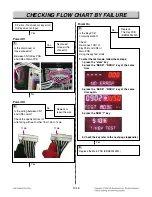
CHECKING FLOW CHART BY FAILURE
Yes
Power Off
2
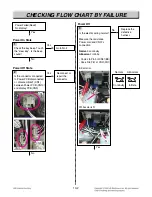
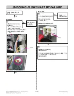
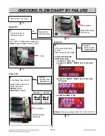
Is the door lock switch
(micro switch) normal?
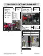
measure the resistance of
door lock switch
normally open type
No
Replace the
micro switch
Yes
Power Off
3
Is the resistance of the
locking motor normal ?
measure the resistance of
locking motor
Normal : approximately 2.6k
Ω
Abnormal : infinite or below 5
Ω
No
Replace the
locking motor
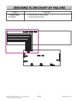
Replace the Relay PCB (EBR52349701)
1
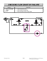
Door Lock System
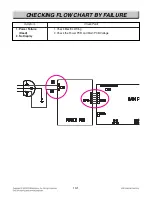
Failure,F-10?
Power Off
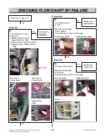
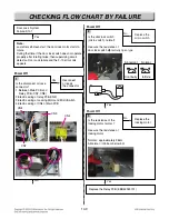
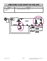
Is the disconnect or loose
connector?
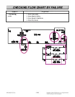
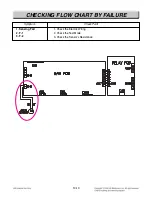
1. Between Main PCB and
Relay PCB (CN7, CN8)
2.Electric wiring of relay PCB(CN9)
3.Electric wiring of Locking Motor and Micro Switch
4.Electric wiring of CN4 of Main PCB
No
Yes
Yes
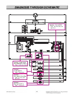
CN9
CN4
CN8
CN8
CN8
CN8
CN8
CN8
CN8
CN8
CN8
CN8
CN8
CN8
CN8
CN8
CN8
CN8
CN8
CN8
CN8
CN8
CN8
CN8
CN7
CN7
CN7
CN7
CN7
CN7
CN7
CN7
CN7
CN7
CN7
CN7
CN7
CN7
CN7
CN7
CN7
CN7
CN7
CN7
CN7
CN7
Reconnect
or repair
the connector
Note :
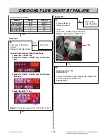
Just after self-clean start, the door lock motor starts to
rotate.
During that time if the door lock switch does not operate
properly after rotating twice, then supervising circuit
detects a Door Lock failure and the F-10 error code
appears.
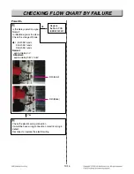
Abnormal
Normal
Continuity
Infinite
Summary of Contents for LSRG309ST
Page 77: ......

