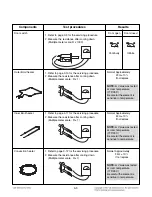
4-10
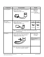
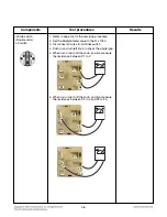
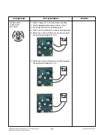
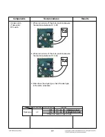
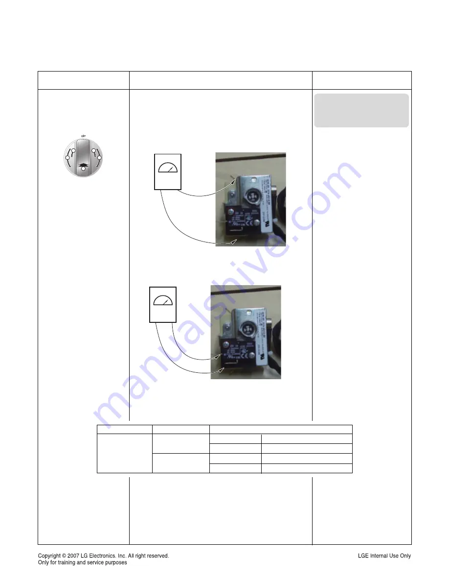
Variable Thermostat :
Lower oven switch
1. Refer to page 3-19 for the servicing procedure.
2. Set the Multiple meter scale to the R x 1000.
3. Disconnect all wires from Variable Thermostat
4. When turn on/turn off the knob, position measure
the resistance between L1 to H.
5. When turn on/turn off the knob, position measure
the resistance between T2 to T3.
6. After check the single type, check the dual type
at the same procedure.
Components
Test procedures
Results
200˚F
Warm
450˚F
400˚F
350˚F
300˚F
250˚F
2
2
1
A
B
L1
T2
T3
T3
T3
T3
T3
T3
T3
T3
T3
T3
T3
T3
T3
T3
T3
T3
T3
T3
H
H
H
H
H
H
H
H
H
H
H
H
H
H
H
H
H
H
L1
T2
T3
T3
T3
T3
T3
T3
T3
T3
T3
T3
T3
T3
T3
T3
T3
T3
T3
T3
H
H
H
H
H
H
H
H
H
H
H
H
H
H
H
H
H
H
NOTE:
Ω
Value was tested
at room temperature
(75F/24˚C)
Part
OFF
ON
L1-H
T2-T3
L1-H
T2-T3
Infinite(open circuit)
Infinite(open circuit)
Continuity(short circuit)
Continuity(short circuit)
Variable
Thermostat
Knob Position
Results
Summary of Contents for LSSE3026ST
Page 55: ...5 3 OVEN LIGHT Warming Drawer CR Cook top Element RR Cook top Element For Model LSE3092ST ...
Page 56: ...5 4 LR Cook top Element RF Cook top Element LF Cook top Element For Model LSE3092ST ...
Page 57: ...5 5 Broil Speed broil Boke Speed roost Warm Proof Easy clean ...
Page 58: ...6 1 COMPOSITION OF CONTROL 6 1 Wiring Diagram ...
Page 92: ... EV COOKTOP PARTS 3056 3215 3079 3006 3016 330M 330H 3205 3022 3204 330S 330S 3014 ...
Page 95: ......

