background image

2-2

USING YOUR OVEN

CONTROL PANEL FEATURES

COMMON FUNCTION

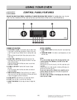
1.  COOK TIME / CLOCK: Touch button and turn the Time/

Temp knob to set the desired amount of time for food to 

cook. The oven shuts off when the set cooking time runs 

out. 

Touch and hold the button for three seconds to set the 

time of day

2.  START TIME / SETTING: Touch button and turn the 

Time/Temp knob to set the delayed start time. The oven 

starts at the set time. 

Touch and hold button for three seconds to select and 

adjust oven settings.

3.  PROBE / LOCKOUT: Touch button to select probe 

function. 

Touch and hold button for three seconds to activate to 

active LOCKOUT.

4.  TIMER ON/OFF (WI-FI): Touch button to set or cancel 

timer on oven. Touch and hold button for three seconds to 

connect the appliance to Wi-Fi network.

5.  OVEN LIGHT: Touch button to turn oven light on/off.

6.  START: Touch button to start all oven features.

7.  SMART  DIAGNOSIS: Use during the Smart Diagnosis 

feature.

OVEN CONTROL 

8.  OVEN MODE KNOB: Turn knob to select oven operating 

mode.

9.  TIME/TEMP KNOB: Turn knob to set temperature or cook 

time for oven.

NOTE:

If F– and a number appear in the display and the oven 

control signals, this indicates a function error code.

Adjust any knob.

Allow the oven to cool for one hour. Put the oven back into 

operation.

If the function error code repeats, disconnect the power to 

the oven and call for service.

If your oven was set for a timed oven operation and a 

power outage occurred, the clock and all programmed 

functions must be reset.

The time of day will flash in the display when there has 

been a power outage.

8

3

5

7

1 2

9

4

6

READ THE INSTRUCTIONS CAREFULLY BEFORE USING THE OVEN. For satisfactory use of your

oven, become familiar with the various features and functions of the oven as described below.

LSWS306ST 

LSWS309BD

Summary of Contents for LSWS300BD

Page 1: ...TION BUILT IN OVEN SERVICE MANUAL MODEL LSWS306ST LSWS309BD LSWS307ST LSWS300BD CAUTION BEFORE SERVICING THE UNIT READ THE SAFETY PRECAUTIONS IN THIS MANUAL P NO MFL37118348 December 2015 Printed in Korea Internal Use Only ...

Page 2: ...er cord is defective it must be replaced by a qualified service agent with a UL listed range cord Electrical leads and cables should not be allowed to touch the oven Rating plate is located on the bracket below the control panel The power supply of the appliance should be turned off when it is being repaired FORWARD LG Electronics assumes no responsibility for any repairs made on our products by a...

Page 3: ...ite Timed cook Delayed timed cook Warm Proof Self clean DISASSEMBLY INSTRUCTIONS 3 1 3 3 Component Locations 3 1 Disassembly instructions 3 2 3 3 Replacing the control panel and related components 3 2 3 3 Removing the SMPS PCB 3 2 Removing the Relay PCB 3 3 Removing the door lock assembly 3 3 Removing the Low Voltage Transformer halogen lamp 3 3 Removing the Serge filter 3 3 DISASSEMBLY INSTRUCTIO...

Page 4: ... lamp 4 2 Oven Thermistor 4 3 Door switch 4 3 Oven lamp 4 3 Broil Element 4 4 Bake Element 4 4 Convection element 4 4 Vent motor 4 4 Composition of control 5 1 5 10 DIAGNOSIS THROUGH SCHEMATIC 6 1 6 4 TROUBLESHOOTING 7 1 7 21 No display No power 7 3 7 4 No heating including F9 F19 error 7 5 7 8 Door lock system failure including F10 F20 error 7 9 7 12 Sensing fail including F1 F2 F4 F5 error 7 13 ...

Page 5: ...e Flammable materials should not be stored in an oven or near surface elements Wear proper apparel Loose fitting or hanging garments should never be worn while using the appliance DO NOT place aluminum foil directly on the oven bottom Children should be kept away from the oven Accessible parts may become hot when the broil is use DISCONNECT power supply cord from the outlet before servicing Replac...

Page 6: ...ed The oven vent could become hot during oven use Never block this vent and never place plastic or heat sensitive items on or near the vent NOTE For proper operation vent trim must be installed Be certain all packing materials are removed from the appliance before operating Keep plastics clothes and paper away from parts of the appliance that may become hot DO NOT force the door open This can dama...

Page 7: ...easily spoil such as milk eggs fish meat or poultry should be chilled in the refrigerator first Even when chilled they should not stand in the oven for more than 1 hour before cooking begins and should be removed promptly when cooking is completed Eating spoiled food can result in sickness from food poisoning Should an oven fire occur leave the oven door closed and turn the oven off If the fire co...

Page 8: ...s is extremely sensitive to the fumes released during an oven self clean cycle Fumes may be harmful or fatal to birds Move birds to well ventilated room Important Instruction In the event the self clean error code F is displayed and error melody sounds the oven is malfunctioning in the self clean mode Switch off the electrical power to the main fuse or breaker and have serviced by a qualified tech...

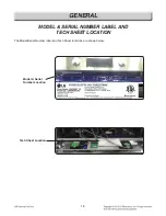
Page 9: ...1 5 GENERAL MODEL SERIAL NUMBER LABEL AND TECH SHEET LOCATION The Model Serial Number label and Tech Sheet locations are shown below Model Serial Number Location Tech Sheet Location ...

Page 10: ...area Lamp 12V 10W 0 8A 2 Left right sides Cooling motor 120V 41W 0 34A Convection motor 120V 42W 0 65A Locking motor 120V 3 5W 0 03A 7 Efficiency Higher than 80 8 Control style Touch screen glass touch Micom 9 Display White LCD Liquid Crystal Display 10 Power control range 170 550 F 77 288 C At bake mode 11 Capacity Overall W H D 4 7 cu ft 622 449 474 24 1 2 17 11 16 18 5 8 12 Capacity Usable 3 2 ...

Page 11: ...ement operates during broil Broil can be used to cook foods which are normally broiled Preheating is not required when using broil All foods should be turned at least once except fish which does not need to be turned Convection Bake Roast Mode Upper element lower element Rear element and fan operate during convection bake Convection bake should be used for cooking casseroles and roasting meats Ove...

Page 12: ... button to turn oven light on off 6 Start Touch button to start all oven features 7 Smart Diagnosis Use during the Smart Diagnosis feature OVEN CONTROL 8 Oven Mode Knob Turn knob to select oven operating mode 9 Time Temp Knob Turn knob to set temperature or cook time for oven NOTE If F and a number appear in the display and the oven control signals this indicates a function error code Adjust any k...

Page 13: ... button to turn oven light on off 6 Start Touch button to start all oven features 7 Smart Diagnosis Use during the Smart Diagnosis feature OVEN CONTROL 8 Oven Mode Knob Turn knob to select oven operating mode 9 Time Temp Knob Turn knob to set temperature or cook time for oven NOTE If F and a number appear in the display and the oven control signals this indicates a function error code Adjust any k...

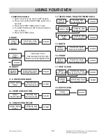
Page 14: ...3 Adjust the time temp knob to the desired setting 12h 24H 4 Press the START button 2 CONVECTION AUTO CONVERSION 1 Select all oven mode knob to OFF position 2 Press and hold the START TIME button for 3 seconds 3 Press the START TIME button 4 Adjust the time temp knob to the desired setting to ENABLE or DISABLE 5 Press the START button 3 THERMOSTAT ADJUSTMENT The oven temperature can be adjusted fr...

Page 15: ...esired temp START Select CRISP CONV Time Temp Knob Set the desired temp START Select CONV ROAST Time Temp Knob Set the desired temp START Select BAKE Time Temp Knob Set the desired temp START Select BAKE Time Temp Knob Set the desired temp START COOK TIME Time Temp Knob Set the desired time START START TIME Time Temp Knob Set the desired time START START TIME Time Temp Knob Set the desired start t...

Page 16: ...ts you on how to service each component inside the range The components and their locations are shown below COMPONENT LOCATIONS Upper Door Switch Upper Oven Light inge nger Upper Door L tch e D Oven Sen or e onvection oto r onvection e ter e e ter in ...

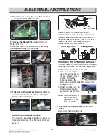
Page 17: ... the Relay PCB Remove the 1 screw and slide Main PCB out Replacing the control panel and related components WARNING ELECTRIC SHOCK HAZARD Unit must be disconnected from electrical outlet when making repairs replacements adjustments Replace all panels before operating oven Failure to do so can result in death or electrical shock CAUTION Be careful when you work on the electric oven handling the she...

Page 18: ...OVEN DOOR MANUALLY In case of need the oven door could be unlocked manually for the service Follow the steps below 1 Disconnect oven from the power source 2 Using a L shaped object close hanger insert it into the gap between the door and the control panel Grasp the hook on the motor and pull towards the left Be careful not to damage the oven 3 While holding the door latch in the Unlocked position ...

Page 19: ... Blade fan Broil elements Convection elements Blade fan Broil elements Convection elements Blade fan Broil elements Convection elements Blade fan Broil elements Convection elements Blade fan Broil elements Convection elements Blade fan Broil elements Convection elements Blade fan Broil elements Convection elements Blade fan Broil elements Convection elements Blade fan Broil elements Convection ele...

Page 20: ...eplace the halogen lamp then reinstall the glass cover Note The above instructions can be used for replacing any of the halogen bulbs in either oven 5 To remove oven temperature sensors Remove the 2 screws from the temperature sensor bracket Pull the temperature sensor forward and remove the connector Mounting Scews 3ea Fan Cover Scews 4ea Outer Inner Cavity Convection Heater Fan Blade Fan Cover W...

Page 21: ...CONTROLLER PARTS Vent motor Thermal limiter Door switch Door switch Door switch Door switch Door switch Door switch Door switch Door switch Door switch Door switch Door switch Door switch Door switch Door switch Door switch Door switch Door switch Door switch Section 2 Section 3 Section 1 WARNING ELECTRIC SHOCK HAZARD Unit must be disconnected from electrical outlet when making repairs replacement...

Page 22: ...perature cools below 14 F 10 C The lower thermostat is located next to lower bake element It opens at 356 F 180 C and closes when the oven temperature cools below 14 F 10 C 3 To remove door switch Remove the 1 screw from the top right panel 4 Squeeze tabs on switch and slide through the front Disconnect the wires from terminals 6 To remove the Thermal limiter Convection motor and Bake Element from...

Page 23: ...re removing the convection fan motor first follow the steps for removing Convection Heater a Disconnect the 2 wire leads and remove the 3 screws from the motor bracket b Separate parts of cavity inner between cavity outer properly refer to the page3 5 About cavity inner disassembly method 3 To remove the hidden bake element a Remove the Vent cover Barrier bracket b Disconnect the 2 wire leads remo...

Page 24: ...MBLY INSTRUCTIONS d Bend the insulator up and remove the 1 screw e Carefully pull the hidden bake element and its BAKE HEATER_COVER out of the oven f When replacing the Bake Element cover use the 5 screws provided ...

Page 25: ...ked position 5 Close the oven door To remove the door 1 Fully open the door 2 Pull the hinge locks down toward Fig 1 the door frame to the unlocked position 3 Firmly grasp both sides of the door at the top 4 Close door to the door removal position which is approximately 5 degrees refer to the Fig 2 5 Lift door up and out until the hinge arm is clear of the slot Slot Hinge lock Lock Unlock Hinge ar...

Page 26: ...dded work surface with the hinge over the edge 3 Remove the two hinge hanger screws 4 Remove the 8 screws Removing the oven door handle glass CAUTION Be careful when you work on the electric oven handling the sheet metal part 4 top liner screws Hinge screws Hinge screws Hinge screws Hinge screws Hinge screws Hinge screws Hinge screws Hinge screws Hinge screws Hinge screws Hinge screws Hinge screws...

Page 27: ...the door liner 6 Lift the hinge out of the door liner slot To remove the oven door glass assembly 7 Lift the COVER_INNER 1 off the door liner 8 Lift the inner oven door glass and bracket assembly out of the door liner COVER_INNER 1 INNER OVEN DOOR GLASS BRACKET ...

Page 28: ...clips are removed 3 Pull the ends of the gasket out of the liner holes REASSEMBLY NOTE When reinstalling the new gasket make sure that all of the clips are seated in their liner holes and that the ends of the gasket are pushed fully into their holes Use the pointed end of a pencil to push the gasket ends into the holes Door gasket Gasket clip Liner Hole ...

Page 29: ...es not fully seated into the connectors 3 Resistance checks must be made with power disabled form oven and with wiring harness or connectors disconnected Before testing any components perform the following checks WARNING Disconnect power supply before servicing Replace all panels and parts before operating Reconnect all grounding devices after servicing Failure to do so can result in death or elec...

Page 30: ...ce Multiple meter scale R x 1000 1 Refer to page 3 2 for disassembly 2 Measure the resistance Multiple meter scale R x 1 Normal Approximately 9 8 Ω 10 Replace if Infinite or below 1Ω Components Test procedures Results NO COM NO COM NO COM Normal Approximately 2550 Ω Replace if Infinite opened below 5 Ω shorted Door latch open Door latch Locked Continuity Infinite NOTE After checking for the contin...

Page 31: ...after cool down Multiple meter scale R x1 Normal Approximately 1090 Ω Replace if Infinite opened below 10 Ω shorted Door open Door closed Continuity Infinite NOTE After checking for the continuity of switch make sure to reconnect leads properly 1 Refer to page 3 7 for disassembly 2 Measure the resistance after cooling down Multiple meter scale R x 1 NOTE Ω Value should be tested at room temperatur...

Page 32: ... resistance after cool down Multiple meter scale R x 1 Normal Approximately 27 9 Ω Replace if Infinite opened 1 Refer to page 3 6 for disassembly 2 Measure the resistance after cool down Multiple meter scale R x 1 Normal Approximately H C 16 Ω L C 20 Ω Replace if Infinite opened below 5 Ω shorted NOTE Ω Value should be tested at room temperature 77F 25 C NOTE Ω Value should be tested at room tempe...

Page 33: ...VI BK BK OR OR OR BK BK RD CONV FAN BLOWER HI RY5 CN01 CN02 RY2 RY4 RY3 RY1 YL BN BL BN VI PK OR BK BK RD HI Relay P C B BREAK RELAY OUTER INNER RY13 RY14 BAKE CONV RY11 BROIL BROIL RY12 RY19 DOUBLE LINE MOTOR DOOR LAMP OVEN LOW BLOWER AC INPUT L2 L1 N 9 8 7 6 5 4 3 2 1 2 3 1 Thermostat 25A 180 C LAMP OVEN LAMP DOOR LAMP OVEN OVEN MOTOR FAN CONV BLOWER FAN LSWS306ST LSWS309BD ...

Page 34: ...VI BK BK OR OR OR BK BK RD CONV FAN BLOWER HI RY5 CN01 CN02 RY2 RY4 RY3 RY1 YL BN BL BN VI PK OR BK BK RD HI Relay P C B BREAK RELAY OUTER INNER RY13 RY14 BAKE CONV RY11 BROIL BROIL RY12 RY19 DOUBLE LINE MOTOR DOOR LAMP OVEN LOW BLOWER AC INPUT L2 L1 N 9 8 7 6 5 4 3 2 1 2 3 1 Thermostat 25A 180 C LAMP OVEN LAMP DOOR LAMP OVEN OVEN MOTOR FAN CONV BLOWER FAN LSWS307ST LSWS300BD ...

Page 35: ...04 VFD Module P N EAJ62608101 Touch PCB P N EBR82172601 Time Temp Encoder PCB P N EBR80595801 Mode Encoder PCB P N EBR80327001 NFC PCB P N EBR78789101 Buzzer PCB P N EBR76332902 Oven Relay PCB P N EBR64624604 Composition of control LSWS306ST LSWS309BD ...

Page 36: ...5 VFD Module P N EAJ62608102 Touch PCB P N EBR82172601 Time Temp Encoder PCB P N EBR80595801 Mode Encoder PCB P N EBR80327001 Wi Fi PCB P N EBR82056903 Buzzer PCB P N EBR76332902 Oven Relay PCB P N EBR64624604 Composition of control LSWS307ST LSWS300BD ...

Page 37: ...5 5 Composition of control Main PCB CN01 CN51 CN20 CN32 CN50 CN44 CN21 CN22 CN42 P N EBR80108104 Relay PCB P N EBR64624604 CN11 CN01 LSWS306ST LSWS309BD ...

Page 38: ...5 6 Composition of control Main PCB P N EBR82864305 Relay PCB P N EBR64624604 CN11 CN01 LSWS307ST LSWS300BD CN60 CN61 CN63 CN52 CN01 CN50 CN53 CN21 CN23 CN33 CN51 ...

Page 39: ...5 7 Composition of control VFD Module P N EAJ62608101 Touch PCB P N EBR82172601 LSWS306ST LSWS309BD ...

Page 40: ...5 8 Composition of control VFD Module P N EAJ62608102 Touch PCB P N EBR82172601 LSWS307ST LSWS300BD ...

Page 41: ...5 9 Composition of control Time Temp Encoder and Mode Encoder P N EBR80595801 P N EBR80327001 NFC and Buzzer PCB P N EBR78789101 P N EBR76332902 LSWS306ST LSWS309BD ...

Page 42: ...5 10 Composition of control Time Temp Encoder and Mode Encoder P N EBR80595801 P N EBR80327001 NFC and Buzzer PCB P N EBR82056903 P N EBR76332902 LSWS307ST LSWS300BD ...

Page 43: ...press the any button 2 press the OVEN LIGHT and turn right Time Temp Encoder at the same time 3 press the OVEN LIGHT and turn right Time Temp Encoder again 4 Select the t0 by move the Time Temp Encoder 5 Press the START button Model Option Software version Only software version and SVC TEST is displayed ...

Page 44: ...u input the START button the relay operation sequence should be as seen below Relay Operation Sequence If want to quit this sequence turn Mode Encoder Bake Inner Broil Outer Broil Conv Heater Blow Fan Lo Blow Fan Hi DLB RY11 RY13 RY14 RY12 RY2 Conv Fan RY3 RY1 RY19 Active Load Icon SW Version Oven ...

Page 45: ...RD HI Relay P C B BREAK RELAY OUTER INNER RY13 RY14 BAKE CONV RY11 BROIL BROIL RY12 RY19 DOUBLE LINE MOTOR DOOR LAMP OVEN LOW BLOWER AC INPUT L2 L1 N 9 8 7 6 5 4 3 2 1 2 3 1 Thermostat 25A 180 C LAMP OVEN LAMP DOOR LAMP OVEN OVEN MOTOR FAN CONV BLOWER FAN Check All heater relays are open shorted Symptom Oven hot F6 Check the Lamp coil s resistance Symptom Oven lamp not operating Check All heater r...

Page 46: ...ROIL BROIL RY12 RY19 DOUBLE LINE MOTOR DOOR LAMP OVEN LOW BLOWER AC INPUT L2 L1 N 9 8 7 6 5 4 3 2 1 2 3 1 Thermostat 25A 180 C LAMP OVEN LAMP DOOR LAMP OVEN OVEN MOTOR FAN CONV BLOWER FAN Check Sensor resistance Symptom Sensor error or no heating F1 F2 F9 Check All heater relays are open shorted Symptom Oven hot F6 Check the Lamp coil s resistance Symptom Oven lamp not operating Check All heater r...

Page 47: ...llowing these steps 1 Press the Any Button 2 Press the OVEN LIGHT and turn right Time Temp Encoder at the same time If the oven has a malfunction the Oven will show the failure Code like FIG 1 If the oven does not have any failure the Oven will look like FIG 2 NOTE After checking the F code move the Mode Encoder to remove all F codes FIG 1 FIG 1 Type of F Code Type of F Code Time of the failure oc...

Page 48: ...CB in case of Key Pad Model F6 Oven hot The oven temperature is over 650 continuously for 2 minutes during cooking ex cept self cleaning Oven Sensor F9 Oven No heating EXCEPT PROOF WARM and EASY CLEAN Starting temperature of 130 or less and the oven door is closed the oven inside tempera ture does not go up more than 10 compared with the starting temperature for 5minutes after the start of cooking...

Page 49: ...7 3 TROUBLESHOOTING Symptom Check Point 1 Power Failure Dead 2 No Display 1 Check Electrical Wiring 2 Check the Main PCB Input Voltage with CN1 CN01 Main PCB Thermostat L1 N WH RD ...

Page 50: ... Yes No 2 Check the connection of Main PCB CN01 Normal Yes No 3 Check the button beep Touch the Clear button Can hear the beep sound No Yes 1 Replace the Main PCB Check the AC input of Main PCB Main PCB CN01 Pin 1 and 3 120V AC Yes No 4 Reconnect Replace the Thermostat Replace the Main PCB Check the Thermostat Normal Short Abnormal Open Normal Yes No 6 Check the connection of L1 and N at Terminal ...

Page 51: ...7 5 TROUBLESHOOTING Symptom Check Point 1 No heating 2 F9 1 Check Electrical Wiring 2 Check Heater s Resistance 3 Check the Sensor ...

Page 52: ...7 6 TROUBLESHOOTING Symptom Check Point 1 No heating 2 F9 1 Check Electrical Wiring 2 Check Heater s Resistance 3 Check the Sensor CN32 ...

Page 53: ...CB Main CN51 Relay CN11 2 Electric wiring of relay PCB All taps 3 Electric wiring of electric element No Yes 1 Unplug the unit Replace the Failed heater Is the connection of heater normal Measure the resistance of each heater The resistance is shown below Yes No 2 CN51 All Taps Broil Inner Outer Conv Heater Bake CN11 Outer Broil Inner Broil Bake Conv Heater ...

Page 54: ...N LIGHT and turn Right Time Temp Encoder at the same time 3 Press the OVEN LIGHT and turn right Time Temp Encoder again 4 press the COOK TIME button Normal Thermistor value at room temp is from 70 to 90 No Yes 3 Current temp Unplug the unit Replace the defective Thermistor Is the resistance of thermistor normal Check Pins 4 and 5 of CN32 in main PCB Normal approximately 1 09kΩ at 25 Yes No 4 CN32 ...

Page 55: ...7 9 TROUBLESHOOTING Symptom Check Point 1 Door Lock System Failure 2 F10 1 Check the Electric wiring 2 Check the Motor s Resistance 3 Check the Relay PCB Door Lock Relay CN32 ...

Page 56: ...7 10 TROUBLESHOOTING Symptom Check Point 1 Door Lock System Failure 2 F10 1 Check the Electric wiring 2 Check the Motor s Resistance 3 Check the Relay PCB Door Lock Relay ...

Page 57: ...of door lock motor Press PROBE button for 3 seconds and try to open the door Does the door open Door lock icon turns on and OVEN LOCKOUT is displayed No Yes 1 Plug in the unit Reconnect If defective harness replace or fix 2 Is the Connector disconnected or loose Check the following 1 Between Main PCB and Relay PCB Main CN51 Relay CN11 2 Electric wiring CN01 of relay PCB 3 Electric wiring of Lockin...

Page 58: ... of door lock switch normally open type Yes 3 No Is the resistance of the lock motor normal measure the resistance of lock motor Normal approximately 2 6kΩ Abnormal infinite or below 5 Ω Yes 4 No Replace the micro switch Replace the lock motor Replace the Relay PCB NC COM Abnormal Normal ...

Page 59: ...7 13 TROUBLESHOOTING Symptom Check Point 1 Sensing Fail 2 F1 3 F2 1 Check the Electrical Wiring 2 Check the Test Mode 3 Check the Sensor s Resistance CN32 ...

Page 60: ...he Connector disconnected or loose 1 Sensor connection 2 CN32 of Main PCB No Yes 1 Plug in the unit Replace the defective Thermistor 2 Is the resistance of thermistor normal Check Pins 5 and 6 of CN32 in main PCB Normal approximately 1 09kΩ at 25 No Yes Sensor connection CN32 CN32 ...

Page 61: ...the test mode follow these steps 1 Press the any button 2 Press the OVEN LIGHT and turn right Lower Time Temp Encoder at the same time 3 press the OVEN LIGHT and turn right Lower Time Temp Encoder again 4 press the COOK TIME button Normal Thermistor value at room temp is from 70 to 90 No Yes 3 Current temp Replace the Main PCB 4 ...

Page 62: ...7 16 TROUBLESHOOTING Symptom Check Point 1 Oven hot 2 F6 1 Check the Resistance of the Relay 2 Check the Sensor s Resistance ...

Page 63: ...7 17 TROUBLESHOOTING Symptom Check Point 1 Oven hot 2 F6 1 Check the Resistance of the Relay 2 Check the Sensor s Resistance CN32 ...

Page 64: ...ective Thermistor Is the resistance of thermistor normal Check Pins 5 and 6 of CN32 in main PCB Normal approximately 1 09kΩ at 25ºC Yes No 1 Unplug the unit Replace the Relay PCB CN32 Bake Heater Relay Convection Heater Relay Inner Broil Heater Relay Tab 10 and Tab 11 RY11 Tab 10 and Tab 12 RY12 Tab 10 and Tab 13 RY13 Tab 10 and Tab 14 RY14 Outer Broil Heater Relay ...

Page 65: ...ain PCB Is the value of thermistor normal Refer below Check with the test mode To enter the test mode follow these steps 1 press the any button 2 press the OVEN LIGHT and turn right Lower Time Temp Encoder at the same time 3 press the OVEN LIGHT and turn right Lower Time Temp Encoder again 4 press the COOK TIME button Normal Thermistor value at room temp is from 70 to 90 No 4 Current temp ...

Page 66: ...7 20 TROUBLESHOOTING Symptom Check Point 1 Key not working 2 F3 Error 1 Check the Door Locking System 2 Check the Electrical Wiring CN44 ...

Page 67: ...Replace the Control panel With Glass Touch PCB And then check button operation using key test mode To enter the test mode follow these steps 1 press the any button 2 press the OVEN LIGHT and turn Right Time Temp Encoder at the same time 3 press the OVEN LIGHT and turn right Time Temp Encoder again 4 press the START TIME button 5 Check the button Refer to the next page appendix No 2 If button is no...

Page 68: ...y is accessed If Key is the normal operation will be the number that corresponds to the Key displayed on the VFD 2 If the key access order was changed the buzzer make double beep sound 3 The buzzer does NOT beep when a key was accessed it would be defected How to stop Key Test mode Press 1st 2nd 8th START KEY OPERATION TEST SEQUENCE ...

Page 69: ...R OR OR BK BK RD CONV FAN BLOWER HI RY5 CN01 CN02 RY2 RY4 RY3 RY1 YL BN BL BN VI PK OR BK BK RD HI Relay P C B BREAK RELAY OUTER INNER RY13 RY14 BAKE CONV RY11 BROIL BROIL RY12 RY19 DOUBLE LINE MOTOR DOOR LAMP OVEN LOW BLOWER AC INPUT L2 L1 N 9 8 7 6 5 4 3 2 1 2 3 1 Thermostat 25A 180 C LAMP OVEN LAMP DOOR LAMP OVEN OVEN MOTOR FAN CONV BLOWER FAN LSWS306ST LSWS309BD ...

Page 70: ... GY WH WH VI BK BK OR OR OR BK BK RD CONV FAN BLOWER HI RY5 CN01 CN02 RY2 RY4 RY3 RY1 YL BN BL BN VI PK OR BK BK RD HI Relay P C B BREAK RELAY OUTER INNER RY13 RY14 BAKE CONV RY11 BROIL BROIL RY12 RY19 DOUBLE LINE MOTOR DOOR LAMP OVEN LOW BLOWER AC INPUT L2 L1 N 9 8 7 6 5 4 3 2 1 2 3 1 Thermostat 25A 180 C LAMP OVEN LAMP DOOR LAMP OVEN OVEN MOTOR FAN CONV BLOWER FAN ...

Page 71: ...ER CONV HEATER BAKE HEATER YL BN BL BN VI PK OR BK BK RD BREAK RELAY OUTER INNER RY13 RY14 BAKE CONV RY11 BROIL BROIL RY12 RY19 DOUBLE LINE Thermostat 25A 180 C BROIL HEATER BROIL INNER BROIL OUTER CONV HEATER BAKE HEATER YL BN BL BN VI PK OR BK BK RD BREAK RELAY OUTER INNER RY13 RY14 BAKE CONV RY11 BROIL BROIL RY12 RY19 DOUBLE LINE Thermostat 25A 180 C Center Broil mode full broil BROIL HEATER BR...

Page 72: ...BAKE HEATER YL BN BL BN VI PK OR BK BK RD BREAK RELAY OUTER INNER RY13 RY14 BAKE CONV RY11 BROIL BROIL RY12 RY19 DOUBLE LINE Thermostat 25A 180 C Conv Bake Conv Roast mode full broil BROIL HEATER BROIL INNER BROIL OUTER CONV HEATER BAKE HEATER YL BN BL BN VI PK OR BK BK RD BREAK RELAY OUTER INNER RY13 RY14 BAKE CONV RY11 BROIL BROIL RY12 RY19 DOUBLE LINE Thermostat 25A 180 C BAKE HEATER BL BN RD B...

Page 73: ...CONV HEATER BAKE HEATER YL BN BL BN VI PK OR BK BK RD BREAK RELAY OUTER INNER RY13 RY14 BAKE CONV RY11 BROIL BROIL RY12 RY19 DOUBLE LINE Thermostat 25A 180 C Self Clean mode full broil BROIL HEATER BROIL INNER BROIL OUTER CONV HEATER BAKE HEATER YL BN BL BN VI PK OR BK BK RD BREAK RELAY OUTER INNER RY13 RY14 BAKE CONV RY11 BROIL BROIL RY12 RY19 DOUBLE LINE Thermostat 25A 180 C BROIL INNER CONV HEA...

Page 74: ... VI PK OR BK BK RD BREAK RELAY OUTER INNER RY13 RY14 BAKE CONV RY11 BROIL BROIL RY12 RY19 DOUBLE LINE Thermostat 25A 180 C BROIL HEATER BROIL INNER BROIL OUTER CONV HEATER BAKE HEATER YL BN BL BN VI PK OR BK BK RD BREAK RELAY OUTER INNER RY13 RY14 BAKE CONV RY11 BROIL BROIL RY12 RY19 DOUBLE LINE Thermostat 25A 180 C ...

Page 75: ...EXPLODED VIEW EV INTRODUCTION 9504 9506 Customer Model Product Code SVC Model MODEL ...

Page 76: ... EV DOOR PARTS 1009 1382 1401 1120 1121 1703 1018 1023 1023 1000 1040 W225 W225 W321 W256 W256 W256 1402 1703 1704 ...

Page 77: ... EV CONTROLLER PARTS 2381 2443 2443 2051 260B 260M 2090 2090 2055 2119 260D 2036 260E 2091 2118 W258 2037 2050 2441 2441 Detail A Detail A Detail A 2042 2047 2041 2043 2044 ...

Page 78: ...6 5414 5014 5010 5611 5611 5503 5718 5505 W258 W258 544A 5506 5507 5562 5550 5540 5550 5550 5514 5441 5451 5561 5505 544A 5513 5602 5601 5601 3022 5021 5512 5512 5516 5515 5515 5401 W230 W259 W259 W259 W230 4002 5407 W232 W233 5406 5561 W230 5508 W241 W236 5410 5080 5090 6001 5132 3015 3015 ...

Page 79: ...ASSEmbly 3511 3029 3605 3603 3604 3602 3601 3013 3018 3044 3144 5527 3311 3312 572L EV ...

Page 80: ......

Reviews: