background image

Any reproduction, duplication, distribution (including by way of email, facsimile or other electronic means), publication, modification, copying or transmission of 

this Service Manual is STRICTLY PROHIBITED unless you have obtained the prior written consent of the LG Electronics entity from which you received this 

Service Manual. The material covered by this prohibition includes, without limitation, any text, graphics or logos in this Service Manual.

Copyright © 2017 LG Electronics Inc. All rights reserved. Only training and service purposes

CAUTION

BEFORE SERVICING THE UNIT, READ THE SAFETY PRECAUTIONS IN THIS MANUAL.
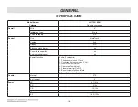
LUTG4519SN

MODEL

:

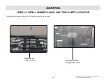
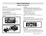
30” Slide-In Gas Double Range

SERVICE MANUAL

P/NO.: MFL37118384

February,2017

Printed in Korea

Summary of Contents for LUTG4519SN

Page 1: ...LG Electronics entity from which you received this Service Manual The material covered by this prohibition includes without limitation any text graphics or logos in this Service Manual Copyright 2017 LG Electronics Inc All rights reserved Only training and service purposes CAUTION BEFORE SERVICING THE UNIT READ THE SAFETY PRECAUTIONS IN THIS MANUAL LUTG4519SN MODEL 30 Slide In Gas Double Range SER...

Page 2: ...on the the back side of rear panel The power supply of the appliance should be turned off when it is being repaired LG Electronics assumes no responsibility for any repairs made on our products by anyone other than Authorized Service Technicians FORWARD DISCONNECT power supply cord from the outlet before servicing Replace all panels and parts before operating RECONNECT all grounding devices Failur...

Page 3: ...t Broil For the Upper oven only Convection bake For the Lower oven only Convection roast For the Lower oven only Warm For both Upper Lower oven Proof For the Lower oven only Lockout For Upper Lower Door lock oven Cooktop control lock Self clean For both Upper Lower oven Easy clean For both Upper Lower oven COMPONENT ACCESS 3 1 3 34 Component Locations 3 1 Removing the Back cover 3 2 Removing the o...

Page 4: ... oven only 3 21 Removing the oven temperature sensors For both Upper Lower oven 3 22 Removing replacing the lift off oven door For the Upper door 3 23 Removing replacing the lift off oven door For the Lower door 3 24 Removing the upper oven door handle glass For the Upper door 3 25 3 26 Reassembling the upper door glass hinge receptacle For the Upper door 3 27 Removing the oven door handle glass F...

Page 5: ...e 8 1 Failure code summary 8 2 Checking flow chart by failure 8 3 8 25 Power Failed Dead No display 8 3 8 5 No heating F9 8 6 8 9 Door Lock System Failure F10 F20 8 10 8 13 Sensing Fail F1 F2 F2 F5 8 14 8 16 Oven hot F6 F16 8 17 8 20 Convection Fan not working F7 8 21 8 23 Key not working F3 Error 8 24 8 25 APPENDIX 9 1 EXPLODED VIEW 10 1 10 7 ...

Page 6: ... the range itself If the range is pulled away from the wall for cleaning service or any other reason ensure that the Anti Tip Device is properly reengaged when the range is pushed back against the wall DISCONNECT power supply cord from the outlet before servicing Replace all panels and parts before operating RECONNECT all grounding devices Failure to do so can result in severe personal injury deat...

Page 7: ...in vibration noise and poor performance of convection when operating Be careful not to scratch or chip the oven liner paint when you remove the oven light socket Turn power OFF before removing the Warming Drawer Be careful when removing and lifting the door DO NOT lift the door by the handle Doing so can result in personal injury as the door is very heavy CAUTION GENERAL IMPORTANT SAFETY INSTRUCTI...

Page 8: ... fitting or hanging garments should never be worn while using the appliance Do Not Use Water on Grease Fires Turn off oven to avoid spreading the flame Smother the fire or flame by closing the door or use dry chemical baking soda or foam type extinguisher Make sure your range is properly adjusted by a qualified service technician or installer for the type of gas natural or LP that is to be used Yo...

Page 9: ... Not Clean Door Gasket The door gasket is essential for a good seal Care should be taken not to rub damage or move the gasket Do Not Use Oven Cleaners No commercial oven cleaner or oven liner protective coating of any kind should be used in or around any part of the oven Clean in the self clean cycle only parts listed in this manual Before self cleaning the oven remove the broiler pan and any uten...

Page 10: ...1 5 GENERAL MODEL SERIAL NUMBER LABEL AND TECH SHEET LOCATIONS The Model Serial Number label and Tech Sheet locations are shown below Model Serial Number Location Tech Sheet Location On Upper Rear Cover ...

Page 11: ...imer Yes Control lock capability Yes Audible preheat signal Yes Special function Setting 7 categories 1 Change hour mode on Clock 2 Convection Auto Conversion On Off 3 Lower oven Temp Adjust 4 Upper oven Temp Adjust 5 Preheat alarm light On Off 6 Beeper volume High Low Mute 7 Select Fahrenheit or Celsius temperature Cooktop Material STS of element 5 Power LR 9 1k 9 1k RR 5k 5k CR 10k 10k LF 12k 10...

Page 12: ...r of Racks 2 Upper 4 Lower Interior oven light 1 Upper 1 Lower Proof Yes Lower warm Yes Lower Broiler pan No Kids meal No Sabbath mode No Dimensions inch Upper oven Interior WxHxD 24 13 16 x 9 1 4 x 20 Lower oven Interior WxHxD 24 13 16 x 14 1 4 x 20 Exterior Width 29 7 8 Exterior Height 36 Cooktop 2111 32 Back Guard Exterior Depth 261 2 Door 2815 16 Handle Net weight Lbs kg 196 2lb 89 0kg Power R...

Page 13: ...isplay shows the changed temperature This feature is called auto conversion The range comes with this feature enabled The oven fan runs while convection baking If the door is left open for longer than 30 seconds during baking the fan stops Broil Mode For the Upper oven only Broil burner operates during broil mode Broil can be used to cook foods which are normally broiled Preheating is not required...

Page 14: ...NTROL KNOB Use to control Left Rear Burner C OVAL CONTROL KNOB Use to control Oval Burner D RIGHT REAR CONTROL KNOB Use to control Right Rear Burner E RIGHT FRONT CONTROL KNOB Use to control Right Front Burner F OVEN MODE KNOB Turn the knob to select oven operating mode G OVEN CONTROL Use to control Oven A B C G F D E ...

Page 15: ...ttings Temp Press the button to change the oven or meat probe temperature during cooking Timer On Off Wi Fi Press the button to set or cancel automatic timer Press and hold button for three seconds to connect to Wi Fi network Press the plus button to increase cooking time or oven temperature Press the minus button to decrease cooking time or oven temperature START Oven Light Press the button to st...

Page 16: ...immer setting almost like the small burner 2 SETTING THE CLOCK 1 Press and hold Cook Time for three seconds 2 Press plus or minus to select the desired time Plus to increase the time and minus to decrease the time 3 Press Start to enter the time and start the clock 3 START CLEAR OFF For both the Upper Lower oven 1 Press START button to start oven 2 Press Upper or Lower CLEAR OFF button 4 TO TURN O...

Page 17: ...n the display 3 Press Start to accept the change 4 PREHEATING ALARM LIGHT ON OFF 1 Press and Hold the Start Time for three seconds 2 Press Start Time repeatedly until PrE Appears in the display 3 Press plus or minus to turn the function on off 4 Press Start to accept the change 5 Beeper Volume 1 Press and Hold the Start Time for three seconds 2 Press Start Time repeatedly until BEEP Appears in the...

Page 18: ...3 or 4 hours 1 Remove all racks and accessories from the oven 2 Turn the oven mode knob to select Self Clean The oven defaults to the recommended four hour self clean for a moderately soiled oven Press plus or minus repeatedly to cycle through self clean times in the upper or lower oven Both ovens cannot use the self clean function at the same time 3 Press Start 15 EASY CLEAN For the Upper Lower o...

Page 19: ...Burner Lower Door Latch Assembly Lower Door Latch Assembly Hinge Hanger Oven Light Oven Light Door Locking Motor Micro Switch Gas Pressure Regulator Lower Bake Heater Igniter Upper Bake Door Locking Motor Micro Switchv Lower Bake Burner Upper Bake Burner Upper Door Switch Lower Door Switch Burner Body Pipe Spark module Igniter Broil Hinge Hanger Oven Valve Igniter Lower Bake ...

Page 20: ...10 screws COMPONENT ACCESS REMOVING THE BACK COVER DISCONNECT power supply cord from the outlet before servicing Replace all panels and parts before operating RECONNECT all grounding devices Failure to do so can result in severe personal injury death or electrical shock WARNING Be careful when you work on the electric range handling the sheet metal part Sharp edge may be present and you can cut yo...

Page 21: ...y PCB Disconnect 2ea connectors REMOVING THE OVEN RELAY PCB POWER PCB POWER RELAY Power Relay PCB Oven Relay PCB DISCONNECT power supply cord from the outlet before servicing Replace all panels and parts before operating RECONNECT all grounding devices Failure to do so can result in severe personal injury death or electrical shock WARNING Be careful when you work on the electric range handling the...

Page 22: ...remove the controller after unplug the 8ea connectors of Main PCB and Cooktop COMPONENT ACCESS REMOVING THE CONTROLLER DISCONNECT power supply cord from the outlet before servicing Replace all panels and parts before operating RECONNECT all grounding devices Failure to do so can result in severe personal injury death or electrical shock WARNING Be careful when you work on the electric range handli...

Page 23: ...he Main PCB supporter COMPONENT ACCESS REMOVING THE MAIN PCB AND KEY PCB ASSEMBLY Buzzer PCB Touch Bridge PCB Encoder PCB Bracket DISCONNECT power supply cord from the outlet before servicing Replace all panels and parts before operating RECONNECT all grounding devices Failure to do so can result in severe personal injury death or electrical shock WARNING Be careful when you work on the electric r...

Page 24: ... COMPONENT ACCESS REASSEMBLY NOTE When you reinstall the Key PCB Assembly make sure that the upper brackets of it are inserted into the correct guide then reinstall the lower bracket screw Key PCB Wi fi PCB ...

Page 25: ...he cooktop 5 Remove the vent bracket 6 Lift top up at front NOTE Before lowering the top line up the burner body and with the cooktop to replace screws COMPONENT ACCESS REMOVING THE COOKTOP PLATE DISCONNECT power supply cord from the outlet before servicing Replace all panels and parts before operating RECONNECT all grounding devices Failure to do so can result in severe personal injury death or e...

Page 26: ...rews of the manifold 6 Remove 11EA hex Phillips head screws on the cook top And lift it 7 You can find cooling fan Please be assembled with a screws 3 EA the cooling fan COMPONENT ACCESS DISCONNECT power supply cord from the outlet before servicing Replace all panels and parts before operating RECONNECT all grounding devices Failure to do so can result in severe personal injury death or electrical...

Page 27: ...valve 4 To remove the IGT a Remove the cooktop plate See REMOVING THE COOKTOP PLATE on page 3 7 b Remove 2 screws from IGT COMPONENT ACCESS Screw Seal Valve Screw Valve Seal Single Burner valve Fitting REMOVING THE COOKTOP PARTS DISCONNECT power supply cord from the outlet before servicing Replace all panels and parts before operating RECONNECT all grounding devices Failure to do so can result in ...

Page 28: ... for the procedure b Pry on the 2 release tabs and slide the switch off the valve stem c Remove the 2 connectors and remove the ignition switch 6 To remove the electrode spark plug a Remove the connector from the spark module b Stretch the electrode bracket c Remove the electrode from the burner housing COMPONENT ACCESS ...

Page 29: ...or latch and remove the latch b Remove the door latch from the burner box and unhook the actuating rod Unhook Actuating Rod DISCONNECT power supply cord from the outlet before servicing Replace all panels and parts before operating RECONNECT all grounding devices Failure to do so can result in severe personal injury death or electrical shock WARNING Use caution when handling sheet metal parts whil...

Page 30: ... cooling fan see page 3 2 3 4 3 6 and 3 8 for the procedure b Remove the upper case c Remove the upper door switch from the range To do this squeeze tabs and use a ratchet extension or a small socket and tap it out of the hole with a hammer Door Switch d Disconnect the wires from the terminals Wires COMPONENT ACCESS ...

Page 31: ...etween Upper Lower cavities 2 screws b Remove 4 screws from upper and lower wool cover back 4 Screws d Tilt Upper cavity cautiously make sure that the controller does not fall down to the floor DISCONNECT power supply cord from the outlet before servicing Replace all panels and parts before operating RECONNECT all grounding devices Failure to do so can result in severe personal injury death or ele...

Page 32: ...ck cover cooktop plate manifold panel and cooling fan see page 3 2 3 4 3 6 and 3 8 for the procedure b Remove the Side panels see page 3 29 for the procedure c Remove the lower door switch from the range To do this squeeze tabs and use a ratchet extension or a small socket and tap it out of the hole with a hammer Door Switch d Disconnect the wires from the terminals Wires COMPONENT ACCESS ...

Page 33: ...n removing the screws make sure holding the broil burner assembly 6 To remove the igniter a Perform step 1 5 on this page b Remove the 2 screws and then remove the igniter COMPONENT ACCESS DISCONNECT power supply cord from the outlet before servicing Replace all panels and parts before operating RECONNECT all grounding devices Failure to do so can result in severe personal injury death or electric...

Page 34: ...e the 2 nuts and then remove flame guide 5 To remove the bake burner assembly Remove the 1 screw and then remove the burner assembly 6 Remove the rear back cover and motor cover see step 2 4 5 on page 3 2 7 Disconnect the igniter plug 8 To remove the igniter Remove the 2 screws and then remove the igniter COMPONENT ACCESS OVEN BOTTOM THE FRAME GUIDE AND THE UPPER BAKE BURNER ASSEMBLY For the Upper...

Page 35: ...over 4 Remove 5 screws of the burner cover U remove the burner cover U 5 Remove the screw from nozzle holder of the back side 6 Remove 2 screws of the bake burner from the burner cover L and then remove bake burner 7 To remove the igniter a Perform step 1 5 on this page b Remove a screw and then remove the igniter LOWER BAKE BURNER ASSEMBLY For the Lower oven only Fan cover burner cover U ...

Page 36: ...l the range out of its mounting location so that you can access the rear of the unit b Remove the screw from the motor cover and then remove motor cover c Disconnect the wire connection and remove the 3 screws Removing the CONVECTION FAN blade and Fan motor For the Lower oven only Be careful not to bend the fan blade Doing so can result in vibration noise and poor performance of convection when op...

Page 37: ...oven you will have to push the socket out from the back of the unit 6 Disconnect the wires from the socket terminals REMOVING THE OVEN LIGHT SOCKET ASSEMBLY DISCONNECT power supply cord from the outlet before servicing Replace all panels and parts before operating RECONNECT all grounding devices Failure to do so can result in severe personal injury death or electrical shock WARNING Use caution whe...

Page 38: ...onnected to latch rod from unlocked position to locked position from locked Position to unlocked position 3 The cam activates the micro switch that causes the motor to stop 4 The locked status remains until the range temperature drops to approximately 500F after end of the self clean or lock out feature is reactivated The motor operates to unlock door at that time DISCONNECT power supply cord from...

Page 39: ...ve the 1 screw from the latch drive 6 Unhook the Latch rod from the cam DISCONNECT power supply cord from the outlet before servicing Replace all panels and parts before operating RECONNECT all grounding devices Failure to do so can result in severe personal injury death or electrical shock WARNING Use caution when handling sheet metal parts while servicing the range Some parts may have sharp edge...

Page 40: ...al parts while servicing the range Some parts may have sharp edges which could result in injury CAUTION REMOVING THE OVEN TEMPERATURE SENSORS For both Upper Lower oven 1 Turn off the electrical supply and gas supply going to the range 2 Open the oven door and remove the racks from the oven 3 To remove an oven temperature sensor a Remove the 1 screw b Disconnect the connector in the back of the ove...

Page 41: ...h hinge Push 5 Lift the door up until it is clear of the hinges about 30 To replace the door 1 Be sure both hinges are in a 30 degree position 2 Slide the door back onto the hinges until you hear a solid click and the release buttons have engaged 3 Fully open the door 4 Push the hinge locks down onto the door frame 5 Close the oven door Close the oven door REMOVING REPLACING THE LIFT OFF OVEN DOOR...

Page 42: ...or at the same angle as the removal position seat the indentation of the hinge arms into the bottom edge of the hinge slots The notch in the hinge arms must be fully seated into the bottom edge of the slots Hinge arm Bottom edge of slot Indentation 3 Open the door fully If the door will not open fully the indentation is not seated correctly in the bottom edge of the slots 4 Lock the hinge locks ro...

Page 43: ...air guide b Remove 2 screws from each handle bracket REMOVING THE UPPER OVEN DOOR HANDLE GLASS For the Upper door DISCONNECT power supply cord from the outlet before servicing Replace all panels and parts before operating RECONNECT all grounding devices Failure to do so can result in severe personal injury death or electric shock WARNING Use caution when handling sheet metal parts while servicing ...

Page 44: ... glass a Remove the 4 top liner screws See step 3 on page 2 25 b Place the door liner assembly on a padded work surface with the hinge receptacles over the edge c Lift the hinge receptacle out of the door liner slot d Lift the inner glass and bracket out of the inner cover Inner cover Hinges on both side ...

Page 45: ...visible in the glass after the door is reassembled REASSEMBLY METHOD OF HINGE RECEPTACLE 1 Cover the inner cover with the door frame 2 Pull up the bottom of the hinge receptacle to align the hole with the hole in the frame then insert and tighten the bottom screw 3 Move the inner cover and pull the top of the hinge receptacle to align with the hole in the frame and insert the second screw in the h...

Page 46: ...e facing up same as Step 2 b Remove 2 screw from the door bottom c Remove 4 screws from middle of door frame COMPONENT ACCESS REMOVING THE OVEN DOOR HANDLE GLASS For the Lower door DISCONNECT power supply cord from the outlet before servicing Replace all panels and parts before operating RECONNECT all grounding devices Failure to do so can result in severe personal injury death or electrical shock...

Page 47: ...29 COMPONENT ACCESS d Lift the door frame out of the inner cover e Remove the hinge hanger assembly and lift the inner glass and bracket out of the inner cover Inner oven door glass and bracket Inner cover ...

Page 48: ...s not visible in the glass after the door is reassembled REASSEMBLY METHOD OF HINGE HANGER 1 Cover the inner assembly into the door frame 2 Fasten 4 screws in the middle of door frame 3 Place the door liner assembly on a padded work surface with the hinge hangers over the edge 4 Fasten 2 screws in the bottom of door fram REASSEMBLING THE DOOR GLASS HINGE HANGER For the Lower Door 4 screws 4 screws...

Page 49: ...ET DISCONNECT power supply cord from the outlet before servicing Replace all panels and parts before operating RECONNECT all grounding devices Failure to do so can result in severe personal injury death or electrical shock WARNING Use caution when handling sheet metal parts while servicing the range Some parts may have sharp edges which could result in injury CAUTION Door gasket Door gasket Gasket...

Page 50: ...nd manifold panel see the page 3 4 and 3 7 for the procedure 6 Remove the screws from the left or right side panel 7 Remove the screw from the left or right manifold bracket DISCONNECT power supply cord from the outlet before servicing Replace all panels and parts before operating RECONNECT all grounding devices Failure to do so can result in severe personal injury death or electrical shock WARNIN...

Page 51: ... 3 33 COMPONENT ACCESS 8 Pull the back of the side panel out from the range approximately 10 9 Push forward and remove the side panel ...

Page 52: ...nd a gas supplier fitting b Remove 2 screws from the wool cover back COMPONENT ACCESS Gas supplier fitting 2 fittings 4 fittings 4 connectors 2 screws Wool cover back 2 screws REMOVE THE OVEN VALVE SAFETY VALVE GAS PRESSURE REGULATOR DISCONNECT power supply cord from the outlet before servicing Replace all panels and parts before operating RECONNECT all grounding devices Failure to do so can resul...

Page 53: ...ctors Therefore disconnecting and reconnecting wires will be necessary throughout test procedures 2 ALL units in the first few days of use should be checked for mis wiring or loose connections Disconnect power supply cord from the outlet before servicing Replace all panels and parts before operating Reconnect all grounding devices after servicing Failure to do so can result in death or electrical ...

Page 54: ...or the servicing procedure 2 Measure the resistance NO COM Door latch open Door latch locked Continuity Infinite NOTE After checking for the continuity of switch make sure that they are connected correctly Oven Sensor 1 Refer to page 3 22 for the servicing procedure 2 Measure the resistance after cooling down Multiple meter scale R x 1000 Normal Approximately 1 09 kΩ 10 If not replace NOTE Oven se...

Page 55: ...n lamp 1 Measure the resistance after cooling down Multiple meter scale R x1 Normal Approximately 25 7 Ω 10 If not replace Igniter Type 1 1 Remove wire leads 2 Measure resistance Normal 45 Ω 400 Ω Room Temperature Resistance Replace if Infinite opened Igniter Type 2 1 Remove wire leads 2 Measure resistance Normal 50 Ω 800 Ω Room Temperature Resistance Replace if Infinite opened ...

Page 56: ...re the resistance after cooling down Multiple meter scale R x 1 Normal Approximately 1 3 Ω If not replace Ignition switch 1 Refer to pages 3 9 3 10 for servicing procedure 2 Measure the resistance by rotating the cam of each switch slowly Multiple meter scale R x 1 approximately 40 80 other Continuity Infinite ...

Page 57: ...500 F BAKE UPPER 12 500 F BAKE LOWER 12 000 G Natural Gas Orifice Specifications BURNER OUTPUT RATINGS BTU HR Natural Gas 5 W C P MODEL BURNER BTU RATE ORIFICE CODE LUTG4519SN LF 12 000 C LR 9 100 V RR 5 000 AA RF 18 500 U CTR 10 000 T BROIL 14 500 I BAKE UPPER 14 500 I BAKE LOWER 14 000 X This conversion must be done by a qualified technician or gas supplier in accordance with the manufacturer s ...

Page 58: ... 5 2 CONVERSION TO LP GAS Orifice Locations for LP Gas LUTG4519SN CONVERSION POINT 1 Regulator 2 Bake burners 3 Broil Burner 4 Surface burners M Q Q G W LR LF RR RF CTR ...

Page 59: ...TOR 1 Check the pressure regulator is located at the rear of the range 2 Unscrew the hex nut cap by using an adjustable wrench 3 Separate plastic cap and hex nut cap by turning the plastic cap 90 4 Assemble plastic cap in the opposite side 5 Screw the hex nut cap back into the regulator Do not over tighten CONVERSION TO LP GAS Plastic Cap LP Pressure Regulator If the gas supply to the range is dis...

Page 60: ...make sure the orifice spud is securely screwed into the nozzle holder 3 CONVERT BROIL BURNER ORIFICES OVEN UPPER BURNER BROIL 1 Remove oven door and broil burner assembly Then remove the wire cover using a Phillips head screwdriver 2 Release the connector of the igniter 3 Remove the orifice spud from nozzle holder using a 13 32 or 10mm wrench 4 Install the LP orifice spud F to the nozzle holder To...

Page 61: ...rifice spuds into conversion kits and place back on the range for possible future conversion NOTE If an orifice spud is accidentally dropped the cooktop can be raised as follows 1 Remove 5EA knobs 2 Using a phillips head screwdriver remove the 2 side the 2 front and the 4 under screws of the manifold 3 Lift manifold up at front 4 Remove the 2 front screws of the cooktop 5 Remove 11EA hex Phillips ...

Page 62: ...face burners 2 Turn the knob on the burner being adjusted to LO 3 Remove knob 4 Insert a small flat blade screwdriver into the valve shaft as shown in Fig 1 Turn the adjustment screw until the flame reaches the desired size 5 Replace the knob Note Hold the valve shaft with one hand while turning the screw for adjustment with the other Fig 1 Center adjustment screw 6 Test The Flame Stability Test 1...

Page 63: ... 6 1 COMPOSITION OF CONTROL Wiring Diagram ...

Page 64: ...f control Main PCB P N EBR81445904 Encoder PCB P N EBR80327001 SMPS PCB P N EBR80595701 Wi Fi PCB P N EBR82056903 Touch PCB P N EBR82864102 Metal Touch System PCB P N EBR82864201 Relay PCB P N EBR80595412 Buzzer PCB P N EBR76332902 Front Back ...

Page 65: ... 6 3 COMPOSITION OF CONTROL Main PCB P N EBR81445904 CN40 CN52 CN64 CN03 CN60 CN63 CN53 CN21 CN50 CN51 CN41 CN61 ...

Page 66: ... 6 4 COMPOSITION OF CONTROL P N EBR80595412 Oven Relay PCB CN53 CN51 CN52 ...

Page 67: ... 6 5 COMPOSITION OF CONTROL SMPS PCB Touch PCB P N EBR80595701 P N EBR82864102 CN02 CN01 CN1 ...

Page 68: ... 6 6 COMPOSITION OF CONTROL P N EBR80327001 P N EBR82056903 P N EBR76332902 P N EBR82864201 Encoder PCB Wi Fi PCB Buzzer PCB Metal Touch System PCB CN41 CON1 CN2 CN1 ...

Page 69: ...Lower CLEAR OFF key 2 Press the button in the following order Upper CLEAR OFF Upper CLEAR OFF hold for 3 seconds 3 Press the START Oven Light button again 4 Select the t0 by press the button 5 Press the START button Model Option Error code Software version Only software version is displayed at the right digits ...

Page 70: ... the START button the relay operation sequence should be as seen below Relay Operation Sequence SVC Test Mode Software Version Active Load Icon Lamp Lock Motor Bake Broil DLB RY 4 RY 3 RY 5 RY 6 RY 7 Lock Motor RY 10 Low C Fan RY 9 High C Fan RY 8 Conv Heater RY 11 DLB RY 7 Upper Oven Lower Oven 1 2 3 4 5 6 7 8 9 10 11 12 Step ...

Page 71: ...relays are open shorted Symptom no heating F9 F19 Check All heater relays and DLB relay are open Symptom Sensor error or no heating F1 F2 F9 F19 Check Sensor resistance Symptom Door lock fail F10 F20 Check relative part Symptom Oven lamp not operating Check the Lamp coil s resistance ...

Page 72: ...OFF key 2 Press the button in the following order Upper CLEAR OFF Upper CLEAR OFF hold for 3 seconds If the oven has a malfunction the Oven will show the failure Code like FIG 1 If the oven does not have any failure the Oven will look like FIG 2 NOTE After checking the F code press the CLEAR button to remove all codes TROUBLESHOOTING FIG 1 FIG 2 Type of F Code Time of the failure occurrence Time o...

Page 73: ...The oven temperature is over 650 continuously for 2 minutes during cooking except self cleaning Oven Sensor F18 Probe short Lower oven probe is shorted 1 Wiring 2 Probe Sensor F9 Upper F19 Lower Oven No heating EXCEPT PROOF WARM and EASY CLEAN Starting temperature of 130 or less and the oven door is closed the oven inside temperature does not go up more than 10 compared with the starting temperatu...

Page 74: ...BY FAILURE Main PCB CN03 CN02 SMPS PCB CN01 Thermostat WH RD Pin No 1 3 4 7 6 7 Vf 4 3V 33V 12V Voltage CN01 CN02 CN03 Symptom Check Point 1 Power Failure Dead 2 No Display 1 Check Electrical Wiring 2 Check the SMPS PCB Input Voltage with CN01 ...

Page 75: ...nect If defective harness replace or fix 1 3 Check the AC input of SMPS PCB SMPS PCB CN01 Pin 1 and 3 120V AC No Yes Go to 7 On the next Page 4 CN1 No No Check the connection of Power Cord Normal Reconnect If defective harness replace or fix 2 No Yes Check the connection of L1 and N at Terminal block Normal Reconnect 5 No Yes Check the Thermostat Normal Short Abnormal Open Normal Replace the Therm...

Page 76: ...ting states between CN02 of SMPS PCB and CN03 of Main PCB Is it OK No Yes Replace the Main PCB 7 Reconnect If defective harness replace or fix If the same phenomenon occurs even though after fixed connection you should replace the Main PCB ...

Page 77: ... Ⓑ Ⓐ Ⓖ Ⓒ Ⓓ Ⓔ Ⓕ Ⓗ Ⓘ Ⓙ RY5 Bake Heater Upper Broil Heater Upper Conv Heater Lower RY6 RY12 RY11 Broil Heater Lower RY7 RY13 L1 L2 Symptom Check Point 1 No heating 2 F9 F19 1 Check Electrical Wiring 2 Check Heater s Resistance 3 Check the Sensor ...

Page 78: ... 8 7 TROUBLESHOOTING CN61 CN60 Symptom Check Point 1 No heating 2 F9 F19 1 Check Electrical Wiring 2 Check Heater s Resistance 3 Check the Sensor ...

Page 79: ...ectric wiring of electric element Yes Reconnect If defective harness Replace or fix 1 Unplug the unit Is the connection of heater normal Measure the resistance of each heater The resistance is shown below No Replace the Failed heater 2 yes No CN51 Main PCB Relay PCB All Taps Upper Broil Upper Bake Conv heater Upper Broil Upper Bake Lower Broil Conv heater Lower Broil ...

Page 80: ...T Oven Light button Normal Thermistor value at room temp is from 70 to 90 Yes Go to No 6 4 No Range Of resistance Plug the unit Is the resistance of thermistor normal Check Pins 4 and 5 of CN60 and pins 5 and 6 of CN61 in main PCB Normal approximately 1 09kΩ at 75ºF 25ºC No Replace the defected Themistor 5 Yes Unplugged the unit 6 Replace the Relay PCB If the unit does NOT work even though the Rel...

Page 81: ... 8 10 TROUBLESHOOTING Symptom Check Point 1 Door Lock System Failure 2 F10 F20 1 Check the Electrical wiring 2 Check the Motor s Resistance 3 Check the Relay PCB Door Lock Relay CN60 CN61 ...

Page 82: ... 8 11 TROUBLESHOOTING Symptom Check Point 1 Door Lock System Failure 2 F10 F20 1 Check the Electrical wiring 2 Check the Motor s Resistance 3 Check the Relay PCB Door Lock Relay ...

Page 83: ...heck the following 1 Between Main PCB and Relay PCB CN51 2 Electric wiring CN52 and CN53 of relay PCB 3 Electric wiring of Locking Motor and Micro Switch 4 Electric wiring of CN60 and CN61 of Main PCB Yes Reconnect If defective harness replace or fix 2 yes No Note Just after self clean start the door lock motor starts to rotate During this time if the door lock switch does NOT operate properly aft...

Page 84: ...eplace the micro switch 3 Abnormal Normal yes Is the resistance of the lock motor normal measure the resistance of lock motor Normal approximately 2 6kΩ Abnormal infinite or below 5 Ω No Replace the lock motor 4 Replace the Relay PCB If the same phenomenon occurs even though after replace Relay PCB you should replace the Main PCB yes ...

Page 85: ... 8 14 TROUBLESHOOTING CN61 CN60 Symptom Check Point 1 Sensing Fail 2 F1 F4 3 F2 F5 1 Check the Electric Wiring 2 Check the Test Mode 3 Check the Sensor s Resistance ...

Page 86: ... Main PCB Yes Reconnect or adjust the connection 1 Unplug the unit No No Is the resistance of thermistor normal Check Pins 4 and 5 of CN60 and pins 5 and 6 of CN61 in main PCB Normal approximately 1 09kΩ at 75ºF 25ºC No Replace the defective Thermistor 2 Yes CN61 CN60 Upper Sensor connection Lower Sensor connection CN61 CN60 ...

Page 87: ...per or Lower CLEAR OFF key 2 Press the button in the following order Upper CLEAR OFF Upper CLEAR OFF hold for 3 seconds 3 Press the START Oven Light button again 4 Select the t3 by press the button and press the START Oven Light button Normal Thermistor value at room temp is from 70 to 90 Yes Go to No 1 3 No Current Oven Temp 4 Replace the Main PCB ...

Page 88: ... F J Ⓑ Ⓐ Ⓖ Ⓒ Ⓓ Ⓔ Ⓕ Ⓗ Ⓘ Ⓙ RY5 Bake Heater Upper Broil Heater Upper Conv Heater Lower RY6 RY12 RY11 Broil Heater Lower RY7 RY13 L1 L2 Symptom Check Point 1 Oven hot 2 F6 F16 1 Check the Resistance of the Relay 2 Check the Sensor s Resistance ...

Page 89: ... 8 18 TROUBLESHOOTING CN61 CN60 Symptom Check Point 1 Oven hot 2 F6 F16 1 Check the Resistance of the Relay 2 Check the Sensor s Resistance ...

Page 90: ...eplace the defective Thermistor 1 Unplug the unit Is the Heater relay normal Measure the resistance of heater relay and L Normal infinite Abnormal shorted No Replace the Relay PCB 2 yes Yes CN61 CN60 Upper Bake Heater Relay Upper Broil Heater Relay Convection Heater Relay Lower Broil Heater Relay Tab 01 and Tab 11 RY5 Tab 01 and Tab 12 RY6 Tab 02 and Tab 21 RY11 Tab 02 and Tab 22 RY12 ...

Page 91: ...r normal Refer below Check with the test mode To enter the test mode follow these steps 1 Press the Upper or Lower CLEAR OFF key 2 Press the button in the following order Upper CLEAR OFF Upper CLEAR OFF hold for 3 seconds 3 Press the START Oven Light button again 4 Select the t3 by press the button and press the START Oven Light button Normal Thermistor value at room temp is from 70 to 90 No Repla...

Page 92: ... 8 21 TROUBLESHOOTING CN42 CN53 Symptom Check Point 1 Convection Fan not working 2 F7 1 Check the Resistance of the Relay 2 Check the Motor s Resistance ...

Page 93: ... No Replace the Fan motor 1 Unplug the unit Is the fan motor relay normal Measure the resistance of fan motor relay and Live Normal infinite Abnormal shorted No Replace the failed heater 2 yes Yes 3th pin and 7th pin of CN53 RY 9 Fan High Fan Low Fan motor Resistance Ω Approximately Fan High 25 10 Fan Low 30 10 5th and 7th pin of CN53 RY 8 Conv Fan High Conv Fan Low ...

Page 94: ...loose Check all connectors and harnesses that are associated with the convection fan No Replace the Main PCB 3 Yes Reconnect If defective harness replace or fix If the same phenomenon occurs even though after fixed connection you should replace the Main PCB ...

Page 95: ... 8 24 TROUBLESHOOTING Symptom Check Point 1 Key not working 2 F3 Error 1 Check the Door Locking System 2 Check the Electric Wiring CN1 CN1 CN53 CN2 ...

Page 96: ...Control panel With Glass Touch PCB And then check button operation using key test mode 1 Press the Upper or Lower CLEAR OFF key 2 Press the button in the following order Upper CLEAR OFF Upper CLEAR OFF hold for 3 seconds 3 Press the START Oven Light button again 4 Select the t3 by press the button and press the START Oven Light button 5 Check the button Refer to the next page appendix 2 No 3 If bu...

Page 97: ...accessed If Key is the normal operation will be the number that corresponds to the Key displayed on the VFD 2 If the key access order was changed the buzzer make double beep sound 3 The buzzer does NOT beep when a key was accessed it would be defected How to stop Key Test mode Press 1st Cook time 2nd 9th Lower CLEAR OFF Key operation Test sequence ...

Page 98: ...EXPLODED VIEW EV INTRODUCTION CONTROLLER PARTS 9504 5080 9506 3913 5532 8511 W229 9381 W229 9381 9384 MODEL Customer Model Product Code SVC Model ...

Page 99: ...UPPER DOOR PARTS EV 1021 1009 170R 1035 1035 170L 1015 1020 173U 173U 1008 102S 102S 102L W243 1000 W222 1801 ...

Page 100: ...LOWER DOOR PARTS EV 1041 1009 1115 1120 102L 1018 173L 102U W243 W222 W222 1100 1704 1704 102L 173L 102U W101 W101 1801 ...

Page 101: ...CONTROLLER PARTS EV 5067 5206 2001 2402 2053 260K 2015 2040 2002 208P 208C 208P 244P 244P 244P 5016 2037 2090 260M 2050 2006 2054 208P 208P 208P 244C 2374 244P 244P ...

Page 102: ...4 3976 G058 3974 3979 3977 3973 3978 3972 7384 2058 521L G035 3950 3980 3952 3953 3935 G039 3982 3951 3981 521R W323 W323 3946 3947 3944 381A 3984 G045 2041 3940 3992 3995 3994 3992 3993 3991 3961 3964 3965 3962 3960 G039 3983 ...

Page 103: ...U 5501 5124 5063 591U 5078 5078 5921 546L 546R 5504 5511 4002 5535 5021 W230 5463 W291 W291 W291 W291 5516 5505 W290 5535 5451 5539 5961 5905 5502 5515 590U 5944 594U 320U W115 5945 5409 5911 5906 5921 W291 W291 590U 5958 533U 5019 W291 ...

Page 104: ...904 5039 5408 W102 591L 5405 5955 5510 3057 5505 5512 5450 5501 5509 5063 4002 W230 5505 533L W124 W233 W232 5545 320L W291 5073 5536 590L 5465 W115 W230 5021 5516 W230 5073 533H W291 W291 W291 W291 W291 W115 W291 3511 594L 6008 6000 5981 6008 8508 9384 8508 3501 381X W129 3006 3947 5019 5032 5014 ...

Page 105: ......

Reviews: