background image

26

White Balance Settings

Setting the WB (White Balance) Mode

You can select one of three modes for white balance adjustment as
follows:

1.

Select [WHITE BALANCE ] option on the [MENU] screen then
press 

, or 

button. The WHITE BALANCE menu appears.

2.

Use 

or 

button to select [WB MODE] option.

3.

Use 

or 

button to select one of three modes for white bal-

ance.

ATW (Auto-Tracing White Balance): In this mode, the color tem-
perature is monitored continuously and thereby white balance is
automatically set. The color temperature range for the proper
white balance is approximately 2 500 - 9 500K. Proper white
balance may not be obtained under the following conditions:
1) The color temperature is out of the 2 500 - 9 500K range.
2) When the scene contains mostly high color temperature

objects, such as a blue sky or sunset.

3) When the scene is dim.

(Continued 

b

)

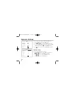
WHITE BALANCE

WB MODE

ATW

RED ADJ
BLUE ADJ

INITIAL SET

ON

RETURN

MENU

LANGUAGE

ENGLISH

CAMERA ID

OFF

EXPOSURE

WHITE BAL

ATW

DAY/NIGHT

AUTO

MOTION DET

OFF

PRIVACY MASK
SPECIAL
INITIAL SET

OFF

EXIT

LVC-SX701PC_AABBSL_ENG  5/20/06  9:47 AM  Page 26

Summary of Contents for LVC-SX701MC

Page 1: ... Camera Instruction Manual Models LVC SX701PC OC MC Before installing operating or adjusting this product please read this instruction booklet carefully and completely LVC SX701PC_AABBSL_ENG 5 20 06 9 47 AM Page 1 ...

Page 2: ...n which case the user will be required to correct the interference at his own expense A suitable conduit entries knock outs or glands shall be provided in the cable entries of this product in the end user Caution Danger of explosion if battery is incorrectly replaced Replaced only with the same or equivalent type recommended by the manufacturer Dispose of used batteries according to the manu factu...

Page 3: ...ry cloth Unplug this prod uct from the wall outlet before cleaning Do not use liquid cleaners 7 Do not block any ventilation openings Install in accordance with the manufacturer s instruc tions Slots and openings in the cabinet are provided for ventilation to ensure reliable oper ation of the product and to protect it from over heating The openings should never be blocked by placing the product on...

Page 4: ...he apparatus 11 Only use attachments accessories specified by the manufacturer 12 Use only the cart stand tripod bracket or table specified by the manufacturer or sold with apparatus When a cart is used use caution when moving the cart apparatus combination to avoid injury from tip over 13 Unplug this apparatus during lightning storms or when unused for long periods of time 14 Refer all servicing ...

Page 5: ...peration 17 18 Language and Camera Identification Settings 19 Exposure Settings 20 24 White Balance Settings 25 27 Day Night Setting 28 Motion Detector Setting MOTION DET 29 30 Privacy Masking Setting 31 Special Menu Settings 32 37 RS 485 Protocol 38 Specifications 39 40 Features This color video camera is designed for use in mon itoring system High resolution and high sensitivity with a 1 3 inch ...

Page 6: ...0Hz DC12V LVC SX701OC Yes No Yes AC24V 60Hz DC12V LVC SX701MC Yes No No AC24V 60Hz DC12V This page shows the differences between the models Models LVC SX701PC are used for the description operation and details provided in this operating guide LVC SX701PC_AABBSL_ENG 5 20 06 9 47 AM Page 6 ...

Page 7: ...id operat ing or storing the unit in the following locations Extremely hot or cold places operating tempera ture 10 C 50 C however we recommend that the unit be used within a temperature range of 0 C 45 C Damp or dust place Places exposed to rain Places subject to strong vibration Close to generators of powerful electromagnetic radiation such as radio or TV transmitters Handling of the unit Remove...

Page 8: ...he lens mount section Remove the lens mount cap before installing a lens sold separately 2 Flange back adjustment dial 3 Flange back lock screw 4 Camera installation bracket The bracket can be fixed at the top or bottom of the camera page 16 LVC SX701PC_AABBSL_ENG 5 20 06 9 47 AM Page 8 ...

Page 9: ... a VIDEO IN connector 7 Power indicator Comes on when the power to the camera is on 8 External Device Connectors RS 485 Connector Connect to an external controller of RS 485 format Alarm Output Terminal ALARM OUT GND Connect to the alarm input of an external device Multi Input Terminal Connect to an external wired remote control 5 6 7 8 LVC SX701PC_AABBSL_ENG 5 20 06 9 47 AM Page 9 ...

Page 10: ...ase put this switch in the DC position ELC When you attach a manual or fixed lens please put this switch in the ELC position VIDEO When you attach an Auto Iris lens requiring the video control signal please put this switch in the VIDEO position 11 Lens iris output connector LENS This 4 pin connector is used to send the Iris control signal and power supply to an auto iris type lens LVC SX701PC_AABB...

Page 11: ... time lapse VCR 2 Use a commercially available AC 24 V adaptor Connect an AC 24 V power source to the AC 24V input terminal on the back of the camera 3 Insert the plug of this power cord into a wall outlet The POWER indicator will light Adjust the pic ture on the monitor using the Brightness and Contrast controls etc To monitor s Video Input or Camera Input 1 2 3 LVC SX701PC_AABBSL_ENG 5 20 06 9 4...

Page 12: ...on on the lens mount then carefully align the lens mount with the camera opening and turn the lens slowly to install it 3 Connect the lens plug to the lens iris output connector LENS on the side of the camera When using lenses from other makers the plug shape may not correspond to the terminal on the camera In such a case remove the original plug and using a soldering iron connect a lens iris plug...

Page 13: ... ALC Lens Setting Switch to the VIDEO position CAUTION Be cautions not to use Auto Iris Lens with over 50mA ELC type auto iris lens Use a manual or fixed iris lens Set the ALC Lens Setting Switch to the ELC position If using a VIDEO type auto iris lens Set the ALC and LEVEL controls on the lens to adjust the iris Normally the ALC volume should be turned all the way to Av Average Depending on the t...

Page 14: ...p p DC 30 V bias voltage on the contact terminal Notes Use a relay unit if the voltage or current of the connected device exceeds the ratings Multi Input Connection Connect an external device to use HOT KEY func tion The HOT KEY function is operated when the input signal is ON To set the HOT KEY function see page 35 The Multi Input terminal has the register of DC 3 3V pull up The sink current must...

Page 15: ...g ring 2 Turn the flange back adjusting ring to obtain a focused point while watching the monitor screen 3 Tighten the flange back fixing screw on the flange back adjusting ring Caution Tightening the screw by force will cause damage to the screw or deviation of focus Note The object may be out of focus when using a source of near infrared light than using the visible light flange back fixing scre...

Page 16: ...ra mounting bracket you should always reuse the screws that have been removed Note If using a camera mounting bracket select a loca tion that is strong enough to bear the full weight of the camera and the mounting bracket for long periods and install the camera and mounting bracket securely LVC SX701PC_AABBSL_ENG 5 20 06 9 47 AM Page 16 ...

Page 17: ... Right button Moves the cursor to the right Use this button to select or adjust the parame ters of the selected item The parameter changes each time this button is pressed Left button Moves the cursor to the left Use this button to select or adjust the parameters of the selected item The parameter changes each time this button is pressed Set button Executes selections and displays a submenu for an...

Page 18: ...the monitor as shown below Check the current settings on the menu Press and hold down for 2 seconds or more to exit the menu screen 18 MENU LANGUAGE ENGLISH CAMERA ID OFF EXPOSURE WHITE BAL PUSH AUTO DAY NIGHT AUTO MOTION DET OFF PRIVACY MASK SPECIAL INITIAL SET OFF EXIT LVC SX701PC_AABBSL_ENG 5 20 06 9 47 AM Page 18 ...

Page 19: ...OFF The camera identification s number is displayed on the lower left of the screen To disappear the number select OFF 1 Select CAMERA ID option on the MENU screen 2 Use or button to select a ID number of the camera MENU LANGUAGE ENGLISH CAMERA ID OFF EXPOSURE WHITE BAL PUSH AUTO DAY NIGHT AUTO MOTION DET OFF PRIVACY MASK SPECIAL INITIAL SET OFF EXIT MENU LANGUAGE ENGLISH CAMERA ID OFF EXPOSURE WH...

Page 20: ...ess Brightness Setting You can set the brightness level 7 levels 1 Select EXPOSURE option on the MENU screen then press or button The EXPOSURE menu appears 2 Use or button to select BRIGHTNESS option 3 Use or button to set the bright level MENU LANGUAGE ENGLISH CAMERA ID OFF EXPOSURE WHITE BAL PUSH AUTO DAY NIGHT AUTO MOTION DET OFF PRIVACY MASK SPECIAL INITIAL SET OFF EXIT EXPOSURE BRIGHTNESS AGC...

Page 21: ...ption 3 Use or button to select a mode OFF AGC is not operated HIGH Applies AGC with high level MEDIUM Applies AGC with middle level LOW Applies AGC with low level MENU LANGUAGE ENGLISH CAMERA ID OFF EXPOSURE WHITE BAL PUSH AUTO DAY NIGHT AUTO MOTION DET OFF PRIVACY MASK SPECIAL INITIAL SET OFF EXIT EXPOSURE BRIGHTNESS AGC MAX MEDIUM SHUTTER AUTO FLIKERLESS OFF BLC WDR OFF LEVEL OFF AREA SPECIAL I...

Page 22: ...tting FLIKERLESS Use for removing the flicker of picture 1 Select EXPOSURE option on the MENU screen then press or button The EXPOSURE menu appears 2 Use or button to select FLICKERLESS option 3 Use or button to set between ON or OFF Set to ON to remove the flicker EXPOSURE BRIGHTNESS AGC MAX MEDIUM SHUTTER AUTO FLIKERLESS OFF BLC WDR OFF LEVEL OFF AREA SPECIAL INITIAL SET ON RETURN MENU LANGUAGE ...

Page 23: ...u use an ordi nary camera when there is an intense and concentrated illumina tion behind an object the back light will shade the image on the monitor screen The BLC function prevents such a back light effect to secure a clear image under all illumination environ ments Continued b EXPOSURE BRIGHTNESS AGC MAX MEDIUM SHUTTER AUTO FLIKERLESS OFF BLC WDR BLC1 LEVEL OFF AREA SPECIAL INITIAL SET ON RETUR...

Page 24: ...The WDR camera is state of the art to enlarge the screen profit effectively especially for taking photos of a window in a building In short it revives both the indoor and outdoor status as they are clearly EXPOSURE BRIGHTNESS AGC MAX MEDIUM SHUTTER AUTO FLIKERLESS OFF BLC WDR USER LEVEL AREA BOTTOM SPECIAL INITIAL SET ON RETURN EXPOSURE BRIGHTNESS AGC MAX MEDIUM SHUTTER AUTO FLIKERLESS OFF BLC WDR...

Page 25: ... BALANCE settings to factory setting select INITIAL SET option then press on the WHITE BALANCE menu 4 To return to the previous menu select RETURN option then press MENU LANGUAGE ENGLISH CAMERA ID OFF EXPOSURE WHITE BAL PUSH AUTO DAY NIGHT AUTO MOTION DET OFF PRIVACY MASK SPECIAL INITIAL SET OFF EXIT WHITE BALANCE WB MODE ATW RED ADJ BLUE ADJ INITIAL SET ON RETURN LVC SX701PC_AABBSL_ENG 5 20 06 9 ...

Page 26: ...and thereby white balance is automatically set The color temperature range for the proper white balance is approximately 2 500 9 500K Proper white balance may not be obtained under the following conditions 1 The color temperature is out of the 2 500 9 500K range 2 When the scene contains mostly high color temperature objects such as a blue sky or sunset 3 When the scene is dim Continued b WHITE BA...

Page 27: ...ress and hold button then release MANUAL You can set the white balance options manually RED ADJ Obtains the optimum amount of red gain BLUE ADJ Obtains the optimum amount of blue gain WHITE BALANCE WB MODE PUSH AUTO RED ADJ BLUE ADJ INITIAL SET ON RETURN WHITE BALANCE WB MODE MANUAL RED ADJ BLUE ADJ INITIAL SET ON RETURN LVC SX701PC_AABBSL_ENG 5 20 06 9 47 AM Page 27 ...

Page 28: ...te mode if the picture is dark or color mode if the picture is bright enough EXT Switches between color picture and black and white pic ture when an external day night switching signal is received NIGHT Black and white mode enabled DAY Color mode enabled Note The AUTO mode is not available if AGC mode is set to OFF or SHUTTER mode is set to a fixed mode MENU LANGUAGE ENGLISH CAMERA ID OFF EXPOSURE...

Page 29: ...Press or button and the MOTION DETECT menu appears 3 Use SENSITIVITY option to obtain the optimum detection level 7 levels 4 Use AREA option to select an area for motion detection 5 To reset the MOTION DETECT settings to factory setting select INITIAL SET option then press on the MOTION DETECT menu 6 To return to the previous menu select RETURN option then press MENU LANGUAGE ENGLISH CAMERA ID OFF...

Page 30: ...turned on Caution Motion detection malfunctions under the following situations Please note the conditions below If shooting an object under flickering fluorescent If leaves or curtains are swayed by the wind Alarm keep low for 1 second after the end of moving picture This function which is Motion Detection Sensitivity has not been evaluated by UL LEFT CENTER TOP BOTTOM RIGHT 1 3 4 15 7 15 4 15 1 3...

Page 31: ...on then use or button to adjust the option H POSITION Moves height position of the mask V POSITION Moves vertical position of the mask H SIZE Enlarge or increase the height size of the mask V SIZE Enlarge or increase the vertical size of the mask 5 To return to the previous menu select RETURN option then press MENU LANGUAGE ENGLISH CAMERA ID OFF EXPOSURE WHITE BAL ATW DAY NIGHT AUTO MOTION DET OFF...

Page 32: ...option 4 To reset the MOTION DETECT settings to factory setting select INITIAL SET option then press on the MOTION DETECT menu 5 To return to the previous menu select RETURN option then press MENU LANGUAGE ENGLISH CAMERA ID OFF EXPOSURE WHITE BAL ATW DAY NIGHT AUTO MOTION DET OFF PRIVACY MASK SPECIAL INITIAL SET OFF EXIT SPECIAL EFFECT OFF D ZOOM USER TITLE SX 700 TITLE DISP OFF HOT KEY NEGA SYNC ...

Page 33: ...ture will be displayed with grayscale V FLIP Flip the picture vertically MIRROR Turn on the mirror effect ROTATE Rotate the picture 180 FREEZE Freeze the picture OFF Turn off the digital effect MENU LANGUAGE ENGLISH CAMERA ID OFF EXPOSURE WHITE BAL ATW DAY NIGHT AUTO MOTION DET OFF PRIVACY MASK SPECIAL INITIAL SET OFF EXIT SPECIAL EFFECT OFF D ZOOM USER TITLE SX 700 TITLE DISP OFF HOT KEY NEGA SYN...

Page 34: ...can name the camera independently 1 Follow steps 1 2 as shown above 2 Use or to select USER TITLE option The first character of the name will blink 3 Use or button to select a character for the first character then press button The second character blink 4 Repeat step 3 to set the remain characters MENU LANGUAGE ENGLISH CAMERA ID OFF EXPOSURE WHITE BAL ATW DAY NIGHT AUTO MOTION DET OFF PRIVACY MAS...

Page 35: ...nction for signal from MULTI INPUT terminal This function is fixed to DAY NIGHT when DAY NIGHT option is set to EXT 1 Follow steps 1 2 as shown above 2 Use or to select TITLE DISP option 3 Use or button to select a function NEGA B W V FLIP MIRROR ROTATE FREEZE or OFF MENU LANGUAGE ENGLISH CAMERA ID OFF EXPOSURE WHITE BAL ATW DAY NIGHT AUTO MOTION DET OFF PRIVACY MASK SPECIAL INITIAL SET OFF EXIT S...

Page 36: ...ck Selects for the operation of multi cameras because it synchronizes the camera phase by using the external signal AC Signal A little phase deviation for some sets may be aligned 5 Use or to select PHASE SHIFT option 6 Use or button to select phase range The PHASE ranges are from 0 to 524 MENU LANGUAGE ENGLISH CAMERA ID OFF EXPOSURE WHITE BAL ATW DAY NIGHT AUTO MOTION DET OFF PRIVACY MASK SPECIAL...

Page 37: ... PIX MAPPING option 4 Use or button to select ON or OFF Caution If you are using manual lens block the lens before using this func tion MENU LANGUAGE ENGLISH CAMERA ID OFF EXPOSURE WHITE BAL ATW DAY NIGHT AUTO MOTION DET OFF PRIVACY MASK SPECIAL INITIAL SET OFF EXIT SPECIAL EFFECT OFF D ZOOM USER TITLE SX 700 TITLE DISP OFF HOT KEY NEGA SYNC INT PHASE SHIFT 000 PIX MAPPING OFF INITIAL SET ON EXIT ...

Page 38: ...x0A 0x0130 therefore C S 0x30 Commands You must send Stop command to camera after sending each command described above The Stop command is 0xC5 0x5F 0x0C 0x00 ID C S BYTE 1 BYTE 2 BYTE 3 BYTE 4 BYTE 5 BYTE 6 0xC5 CODE1 CODE2 CODE3 CAM_ID C S Function Command external device camera OSD Menu ON OFF 0xC5 0x5F 0x25 0x00 ID C S LEFT Button 0xC5 0x5F 0x38 0x00 ID C S Right Button 0xC5 0x5F 0x39 0x00 ID ...

Page 39: ...nization System Internal Line Lock Scanning Frequency 59 94 Hz VD Resolution 540 Lines S N Ratio More than 52 dB AGC Off Standard Illuminance Day 0 001 0 3 DSS Off Lux 1 3 Video Output Night 0 0001 0 02 DSS Off Lux Video Output Signal 1 0 Vp p Composite Signal 75 Ω Auto Gain Control Off Low Medium High Exposure Automatic Control with DC Video Iris meter Electronic Light LVC SX701PC_AABBSL_ENG 5 20...

Page 40: ...Light OFF BLC1 BLC2 USER WDR Motion Detection OFF ON Area Sensitivity Power Consumption Less than 6W Operation Temperature 10ºC 50ºC Humidity 0 RH 80 RH Storage Temperature 20ºC 60ºC Humidity 0 RH 85 RH Weight 250g Dimension H x V x D 67 1 x 59 x 127 5 mm LVC SX701PC_AABBSL_ENG 5 20 06 9 48 AM Page 40 ...

Page 41: ...P NO 3834RS0075Q LVC SX701PC_AABBSL_ENG 5 20 06 9 48 AM Page 41 ...

Reviews: