background image

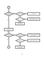
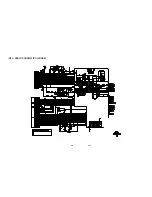
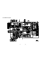
4-17

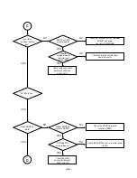
4-18

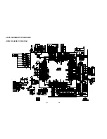
• RF & SERVO SCHEMATIC DIAGRAM

Summary of Contents for LX-D2560A

Page 1: ... SERVICE MANUAL MINI HOME THEATER SERVICE MANUAL MODEL LX D2560A LXS D2560V LX D2960A LXS D2960V ...

Page 2: ...SPEAKER EXPLODED VIEW 2 7 SECTION 3 ELECTRICAL SECTION ELECTRICAL TROUBLESHOOTING GUIDE 3 1 INTERNAL BLOCK DIAGRAM of ICs 3 13 WIRING DIAGRAM 3 25 BLOCK DIAGRAM 3 27 SCHEMATIC DIAGRAMS 3 29 PRINTED CIRCUIT DIAGRAMS 3 41 SECTION 4 DVD PART ELECTRICAL DVD ELECTRICAL TROUBLESHOOTIHG GUIDE 4 1 DVD SCHEMATIC DIAGRAMS 4 15 DVD PRINTED CIRCUIT DIAGRAMS 4 23 SECTION 5 MECHANISM OF DVD PART DECK MECHANISM ...

Page 3: ...ver be touched 4 Laser beams may damage the eyes Absolutely never permit laser beams to enter the eyes Also NEVER switch ON the power to the laser output part lens etc of the pick up if it is damaged 5 Cleaning the lens surface If there is dust on the lens surface the dust should be cleaned away by using an air bush such as used for camera lens The lens is held by a delicate spring When cleaning t...

Page 4: ...tive bag do not place the pick up on the bag This is because there is the possibility of damage by static electricity 4 To prevent AC leakage the metal part of the soldering iron should be grounded 5 Workers should be grounded by an armband 1M Ω 6 Care should be taken not to permit the laser pick up to come in contact with clothing in order to prevent sta tic electricity changes in the clothing to...

Page 5: ...harges sufficient to damage ESD devices 5 Do not use freon propelled chemicals These can generate electrical charges sufficient to damage ESD devices 6 Do not remove a replacement ESD device from its protective package until immediately before you are ready to install it Most replacement ESD devices are packaged with leads electrically shorted together by conductive foam aluminum foil or comparabl...

Page 6: ...se audio 40 20000 Hz Signal to noise ratio audio More than 75 dB 1 kHz Signal to noise ratio video More than 55 dB 1 kHz Dynamic range audio More than 80 dB Video output 1 0 V p p 75Ω S video output Y 1 0 V p p 75Ω C 0 3 V p p 75Ω Component Video output Y 1 0 V p p 75 Ω Pb Pr 0 7 V p p 75Ω Speakers Speaker Name Front Speaker L R Type Bass Reflex 2Way 3Speaker LXS D2960V Model Bass Reflex 2Way 2Spe...

Page 7: ... 1 6 ...

Page 8: ... 251 250 MAC 257 463 262 261 463 463 A48 259 274 A44 273 276 A46 265 264 A50 A47 300 450 SMPS MAIN DVD FRONT 252 2 1 2 2 NOTE THE EXCLAMATION POINT WITHIN AN EQUILATERAL TRIANGLE IS INTENDED TO ALERT THE SERVICE PERSONNEL TO THE PRESENCE OF IMPORTANT SAFETY INFORMATION IN SERVICE LITERATURE ...

Page 9: ...2 3 2 4 2 DECK MECHANISM EXPLODED VIEW 5 CHANGER A26 003 075 023 011 038 073 037 032 062 031 004 005 006 007 001 002 071 431 074 072 ...

Page 10: ...2 5 2 6 3 TAPE DECK MECHANISM 1011 1013 1009 1009 1003 1002 1007 1037 1006 1018 1017 1019 1020 1021 1022 A001 1023 A000 1025 A002 1015 ...

Page 11: ......

Page 12: ... 2 7 4 SPEAKER EXPLODED VIEW 758 757 A700 756 754 755 753 752 751 750 759 ...

Page 13: ... 2 8 ...

Page 14: ...Troubleshooting Check if IC101 KIA7042 input is over 5V Check if output voltage of IC101 KIA7042 is 4 3V Check the related part of IC101 KIA7042 Replace the related parts OK Check power of both terminals of IC101 KIA7042 Check IC100 78KO KF2 1 PIN power OK YES NO NO NO NO YES YES YES YES MICOM PART CHECK I ...

Page 15: ...Check IC103 8PIN IC100 19 20 59 PIN 5V Check the working condition X101 32 768kHz X100 9 8304MHz OK Check P7904 5PIN 5 6V Refer to SMPS Troubleshooting Check D101 1SR35 output is working on 5V Check the related part OK Replace the related parts Check power of both terminals of D101 1SR35 Check Q101 EMITTER 5V and COLLECTOR 5V NO NO NO NO NO YES YES YES YES YES YES YES YES YES YES YES YES MICOM PAR...

Page 16: ...sembly Check power of each PIN OK Replace the related part OK Check P7904 1 2 3 power F1 F2 both terminals over 3 7V Check power VKK over 26V Check P7302 connection condition and power F1 F2 both terminals over 3 7V Check power VKK over 26V Check 25 PIN 5 6V Check IC301 PT6324 power 50 PIN VKK 26V 9 52 PIN 5V YES YES YES YES YES YES YES YES YES YES NO NO NO NO NO NO IC103 KS4CD21CS CHECK FLD DISPL...

Page 17: ...LK When 5V fails check D3191SR35 input and output power Check the related part Check 76 PIN DO DATA input Check the related part Replace the related part OK Replace the related part OK FLT light on OK IC100 75 PIN STB 77 PIN 4PIN DI 78 PIN 1PIN CLK Check Data output YES YES YES YES YES YES YES YES NO NO NO NO ...

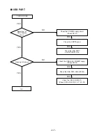
Page 18: ...22 29 39 47 56 65 72 87 94 Check X601 2PIN 3 3V Refer to SMPS Troubleshooting Check the related part of X601 OK Check R668 470Ω output OK Check resistance output of LINE DATA R671 CLK R670 RST R665 OK Check DVD ASS Y PS9829 communication condition P7403 Check IC604 PS9829 DATA input OK Check IC604 PS9829 part Replace the related part Replace the related part Replace the related part Refer to DVD T...

Page 19: ...MODULATOR input of each IC 4 6 14 16 PIN Check POWER IC 700 701 702 703 34 29 27 20 PIN output Check output LINE COIL OK Refer to SMPS Troubleshooting Check resistance power of each LINE IC700 R702 701 726 727 724 IC701 R730 729 750 753 752 IC702 R756 755 768 771 770 IC703 R774 773 794 797 796 Replace the related parts YES YES YES YES YES YES NO NO NO POWER AMP PART CHECK ...

Page 20: ...aveform Check IC801 MC4580 2 6PIN input waveform OK Check IC200 BU4052 16PIN VDD 8PIN VSS power Check u COM IC301 83PIN 84PIN communication Refer to SMPS Troubleshooting Replace the related parts Check IC801 MC4580 4PIN VSS 8PIN VDD power Replace the related parts YES YES YES YES YES YES NO NO NO NO AUX FUNCTION ...

Page 21: ...rts Check IC801 MC4580 4PIN VSS 8PIN VDD power Check IC200 BU4052 1 12PIN input waveform Check IC200 BU4052 3 13PIN output waveform Check IC601 BU 4502 2 15PIN Check 25 PIN 5 6V Check IC801 MC4580 2 6PIN input waveform OK TAPE PCB ASS Y Check IC801 MC4580 2 6PIN input waveform OK Check IC200 BU4052 2 1 5PIN input waveform Check IC200 BU4052 3 13PIN output waveform Check IC601 BU4052 2 15PIN input ...

Page 22: ...efer to SMPS Troubleshooting Check DECK HEAD input Check DECK HEAD input IC201 32 39 PIN Replace the HEAD WIRE and Mecha Replace the related parts Replace the related parts Check the related part OK Check IC202 10 PIN HIGH is working Check the related part OK YES YES YES YES YES YES YES YES YES NO NO NO NO NO NO TAPE PLAY PART CHECK ...

Page 23: ... BASE HIGH Check IC202 4 PIN HIGH working Refer to SMPS Troubleshooting Replace the related parts Replace the related parts OK Check P7207 2 4 output Check P2707 5 7 input Check IC203 MC4580 1 7 Check IC201 10 21 PIN output Check L203 2 3 PIN oscillation Check P2203 5 3 PIN input Check 8 PIN ERASE input OK YES YES YES YES YES YES YES YES YES YES YES NO NO NO NO NO NO NO NO TAPE REC PART CHECK ...

Page 24: ...Of C950 C951 If DC V is in 35V 35V Chcek the DC V Of C909 C903 C921 If DC V is in 14 19V and it is steady Replace the fuse Check BD901 LF901 902 Check IC901 902 Replace IC 901 902 Check short of P9702 line Check short of P9701 line Check short of P9701 P9702 line MAIN PART YES NO YES YES YES YES YES NO NO NO NO NO SMPS POWER CIRCUIT ...

Page 25: ...2 Check the PIN6 OF P9702 If DC V is over5 6V OK Check power circuit Trouble shooting P SENS PART Check the PIN3 OF P9702 If DC V is over 28V 2 OK Check power circuit Trouble shooting VKK PART YES YES NO NO ...

Page 26: ... 3 13 INTERNAL BLOCK DIAGRAM of ICs UTC MC4580 PIN CONFIGURATION TEST CIRCUIT ...

Page 27: ...14 NJM 2279 BLOCK DIAGRAM 6dB 75Ω 6dB 75Ω Vout1 Vout2 Driver Driver V MUTE1 SW2 20kΩ Vin1 Vin2 Vin3 SW1 MUTE2 GND1 GND2 V 20kΩ 20kΩ 20kΩ 20kΩ 4 14kΩ 4 14kΩ 4 45kΩ 4 45kΩ AMP AMP MBM29LV160TE BLOCK DIAGRAM ...

Page 28: ... 3 15 HY57V281620ETP FUNCTIONAL BLOCK DIAGRAM FAN8082D Internal Block Diagram ...

Page 29: ... 3 16 BU2090 Block diagram ...

Page 30: ... 3 17 HA12237F BLOCK DIAGRAM ...

Page 31: ... 3 18 BA3308 BA3308F BLOCK DIAGRAM BA3308 BA3308F ...

Page 32: ... 3 19 TAS5142 BLOCK DIAGRAM ...

Page 33: ... 3 20 HT1200 4 SYSTEM BLOCK DIAGRAM ...

Page 34: ... 3 21 HT1200 4 FUNCTIONAL BLOCK DIAGRAM ...

Page 35: ... 3 22 CS5340 BLOCK DIAGRAM BU4052 BLOCK DIAGRAM ...

Page 36: ... 3 23 STR S6757IF1905 BLOCK DIAGRAM STR A6200 BLOCK DIAGRAM ...

Page 37: ... 3 24 ...

Page 38: ...3 25 3 26 WIRING DIAGRAM ...

Page 39: ...ER HEAD WOOFER DVD DATA CLK OPTICAL USB DA 5V OP AMP EXPENDER DECK HA12237 TAPE IC BU4052 OP AMP CS5340 TUNER MODULE NEC AUDIO MICOM PS9829A PWM MODUL ATOR TAS5142 Power Amp H P_SW PWM OUT DVD CD BLOCK DECK AD MODE A B SOL A RM OP AMP RDS DATA CLK PLL DAT CLK BU4052 DATA CS5340 RESET DVD DATA CLK 12 28MHz TUNER L R TAPE L R AUX L R AUX L R MIC INPUT SOL B MOTER HIGH NO HALF A B REC F R REC MUTE RE...

Page 40: ...CDDVDCT VRDVD VRD LDO1 LDO2 OPEN CLOSE SLED F T 48MHz 27MHz LOAD SPINDLE USB_RESET D D HD 0 15 CONTROL SIGNAL MCU_INTQ JRD HWR MS_SEL_OU HA0 HD 0 7 FOCUS SLED SPINDLE TACKING AMP_STBY DSCK CKE CSo RAS0 CAS WE DQMX LA 0 21 LD 0 7 WRLL MRST LOE AUDIO JACK VIDIO OUT P UP M DECK MECHANISM MOTOR DRIVE IC USB CON USB UBI9021 SWITCH OPT IN OPT OUT ADC PWM DAC MICOM SDRAM MPEG ESS6838 FLASH EEPROM ...

Page 41: ...3 31 3 32 µ COM INTERFACE PWM SCHEMATIC DIAGRAM ...

Page 42: ...3 33 3 34 6CH_AMP SCHEMATIC DIAGRAM ...

Page 43: ...3 35 3 36 FRONT SCHEMATIC DIAGRAM ...

Page 44: ...3 37 3 38 SMPS SCHEMATIC DIAGRAM ...

Page 45: ...3 39 3 40 DECK SCHEMATIC DIAGRAM ...

Page 46: ...3 41 3 42 PRINTED CIRCUIT DIAGRAMS MAIN P C BOARD ...

Page 47: ...3 43 3 44 MAIN P C BOARD ...

Page 48: ...3 45 3 46 FRONT P C BOARD ...

Page 49: ...3 47 3 48 SMPS P C BOARD ...

Page 50: ...3 49 3 50 DECK P C BOARD ...

Page 51: ......

Page 52: ...at FLD Check the voltage of each pin on P5701 Check DVD MD Module Check connector P7501 Reconnect it OK Does AUX FM 87 5 appear at FLD Does it appear DVD ERROR at FLD PUSH KARAOKE DVD BUTTON Check Connector P4405 P4407 P4408 Check an Audio Micom or interface reconnect P4703 OK Does No DISC or Time are appeared at FLD NO NO NO NO NO YES YES YES YES YES ...

Page 53: ...is damaged CHECK THE OUTPUT SIGNAL OF ES8381 TO IC401 FOR CONTROL OPEN CLOSE Check the Tray control I O Pin on IC401 OPEN CLOSE signals on IC401 are OK Load load signals on P4408 are OK Check the cable connection between DVD PCB and MD MECHA Does first tray move inside when it is at closed position ES8381 VIDEO outputs properly Check connection lines between FLASH ES8381 or the FLASH access time w...

Page 54: ...s outputs to motor driver Proper F F outputs Check the motor driver IC401 Check Focus connection on ES8381 and motor driver IC Check the related circuit of SLED and Motor driver IC IC401 Check the MD Check cable connection with pick up head Do not put in disc and tray close Optical Lens is moving for searching Focus B C YES YES YES YES YES YES YES NO NO NO NO NO NO ...

Page 55: ...able connection between P4407 and MD Check the SPINDLE control of motor driver IC404 Check the SPINDLE related circuit on ES8381 Check the related circuit of laser power transistor Check the laser power circuit between ES8381 and power transistor Q405 Q406 Collector voltage of power transistor is ok Q405 Q406 Put disc in tray Does SPINDLE rotate D YES YES YES YES YES YES YES NO NO NO NO NO NO ...

Page 56: ...gnal Check the related circuit between IC401 and ES8381 Check the Tracking control on motor driver IC401 Proper FOO signal on IC401 Check cable connection between P4405 and MD Proper TRO signal on IC401 T T output properly Check cable connection on pick up head Check RF signal waveform Track On OK Disc play YES YES YES YES YES YES NO NO NO NO NO NO NO ...

Page 57: ...gnal data on P4703 is OK Check the MAIN PCB Picture signal data on ES8381 is OK For example composite video Check the video mute TR Q411 Output of Video buffer IC IC407 and ES8381 video signal data Check the connections between ES8381 and P4703 NO NO NO NO YES YES ...

Page 58: ...eck OK Check the POWER supply circuit Check P5701 Check the HRST signal Check the USB PART and DVD PART line Check the USB JACK POWER supply Check P4302 Check the USB DATA LINE P4302 Check the IC405 UBI9021 Check DATA LINE PIN 14 17 20 23 NO NO YES YES YES YES YES YES YES ...

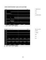
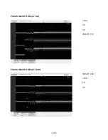
Page 59: ... 4 8 WHEN POWER ON RESET DATA ETC WAVEFORM 1 RESET DVD 2 RX 3 TX 4 LCS3 FLASH Playing at USB function 1 HRST 2 5V 3 D 4 D ...

Page 60: ... 4 9 OPEN CLOSE WAVEFORM AT POWER ON STARTING ACTION WAVEFORM IN MD DEVICE 1 Limit SW 2 OPEN 3 CLOSE 1 SLO from MPEG 2 SLED 3 SLED At Power on ...

Page 61: ... 4 10 FOCUS WAVEFORM AT CD FOCUS WAVEFORM AT DVD 1 FDO 2 F 3 F INSERT CD INSERT DVD 1 FDO 2 F 3 F ...

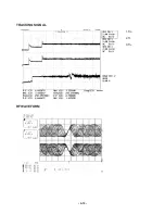
Page 62: ... 4 11 1 Spind 2 Spin 3 Spin 1 A 2 B 3 C 4 D AT POWER ON SPINDLE SIGNAL AT MD DECK AT FIRST ACTION FOCUS SIGNAL A B C D ...

Page 63: ... 4 12 TRACKING SIGNAL RF WAVEFORM 1 Tro 2 Tr 3 Tr ...

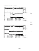
Page 64: ... 4 13 DISK TYPE JUGEMENT WAVEFORM 1 F 2 FDO 3 SVRRF DVD CD ...

Page 65: ... 4 14 ...

Page 66: ...4 15 4 16 DVD SCHEMATIC DIAGRAMS MPEG SCHEMATIC DIAGRAM ...

Page 67: ...4 17 4 18 RF SERVO SCHEMATIC DIAGRAM ...

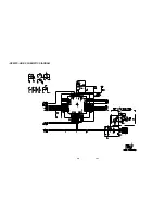
Page 68: ...4 19 4 20 AV SCHEMATIC DIAGRAM ...

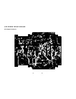
Page 69: ...4 21 4 22 USB PC LINK SCHEMATIC DIAGRAM ...

Page 70: ...4 23 4 24 DVD PRINTED CIRCUIT DIAGRAMS DVD MAIN P C BOARD ...

Page 71: ...4 25 4 26 DVD MAIN P C BOARD ...

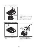
Page 72: ...irection of left right side and lift it up 1 Release 5 Screws 2 Seperate 2 Stoppers connected to Cover S and Clamp Ass y from the Cover S In case of not seperating easily use a gim let or a screwdriver to seperate it as shown in the picture 3 Widen a both sides of Cover S caution of permanent transformation and lift it up from the Ass y Damper 4900RB0005A Traverse Ass y 6717R D001B Mechanism Ass y...

Page 73: ... PH Ass y soldered on the back side PCB Ass y of Mechanism Ass y and then lift up the Frame LG 1 Turn the Gear Cam to counterclockwise and then down the Clamp Ass y as shown in the picture 2 Release 3 Screws attached in the Clamp Ass y 3 Lift up the Clamp Ass y and seperate it Clamp Ass y 4260RZ0004A Gear Cam Frame LG Ass y PWB PH Ass y Wire PCB Ass y 6871RZ0045A ...

Page 74: ...k the Frame LG locking Tab and lift it up as shown in the picture 1 Turn the Gear Cam to counterclockwise and then lift up the FL Base to the top 2 Pull front the Drawer Ass y and push the left right side of Chassis at the end and then seperate the Drawer Ass y PWB PH Ass y 6871RZ0045B Locking Tab FL Base Chassis Drawer Ass y Gear Cam Locking Tab Spring C Arm SW C 4260RZ0001C ...

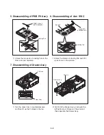
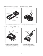
Page 75: ...er remove the Belt from the top of the Chassis 1 Release the Screws big 2 small2 that connects between the Chassis and the PCB Ass y and then seperate the PCB Ass y from the Chassis 2 At this moment remove the solder because the Wire of PCB SW Ass y is soldered on PCB Ass y Drawer L 3210RZH001A Drawer R 3210RZH002A Carriage 3390RZ0002A E PCB Ass y 6871RZ0022A PCB Ass y 6871RZ0022A Belt 4400RZ0002A...

Page 76: ... seperate the PCB SW Ass y 4 Remove the solder on the Motor and the PCB Ass y 5 Lift up the PCB Ass y 1 Release the 2 Screws which fixes the Chassis and the Motor and then se perate it 1 Release the 2 Screws which fixes the Bracket of Solenoid Ass y and then seperate the Solenoid PCB Ass y 6871RZ0045C Motor 4681RZ0001A Solenoid Ass y 6768RZVP01A ...

Page 77: ...5 6 ...

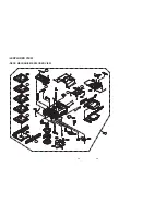
Page 78: ...5 7 5 8 EXPLODED VIEW DECK MECHANISM EXPLODED VIEW A26 003 075 023 011 038 073 037 032 062 031 004 005 006 007 001 002 071 431 074 072 ...

Page 79: ......

Reviews: