background image

Owner’s Manual   7

Introduction

Controls

Controls

Connection Options

Connection Options

R

(  )

(  )

(  )

(  )

L

VIDEO

INPUT

RS-232C INPUT

(CONTROL/SERVICE)

EXTERNAL SPEAKER

Y

P

B

P

R

(MONO)

R

AUDIO

L

R

AUDIO

L

S-VIDEO

AC INPUT

AUDIO INPUT

AUDIO INPUT

AUDIO INPUT

REMOTE

CONTROL

COMPONENT INPUT

DVI INPUT

RGB INPUT

RGB OUTPUT

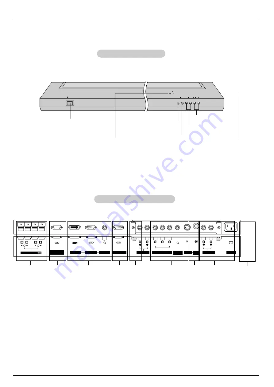
1

1.

EXTERNAL SPEAKER (8 ohm output)

Connect to optional external speaker(s).
* For further information, refer to ‘Speaker & Speaker

Stand’ manual.

2.

RS-232C INPUT (CONTROL/SERVICE) PORT

Connect to the RS-232C port on a PC.

3.

DVI (Digital Visual Interface) INPUT/
RGB INPUT/AUDIO INPUT JACKS

Connect the monitor output connector of a PC to the appro-
priate input port.

4.

RGB OUTPUT JACKS

You can watch the RGB signal on another monitor, connect
RGB OUTPUT to another monitor’s PC input port.

5.

EXPANDED INPUT

6.

COMPONENT INPUT/AUDIO INPUT JACKS

Connect a component video/audio device to these jacks.

7.

REMOTE CONTROL

Connect your wired remote control to the remote control
port on the Monitor.

8.

S-VIDEO INPUT

Connect S-Video out from an S-VIDEO VCR to the S-VIDEO
input.

AUDIO/VIDEO INPUT JACKS

Connect audio/video out from external equipment to these
jacks.

9.

POWER CORD SOCKET

This Monitor operates on an AC power. The voltage is indi-
cated on the Specifications page. Never attempt to operate
the Monitor on DC power.

Back Connection Panel

Back Connection Panel

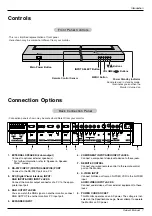
Front Panel Controls

Front Panel Controls

2

4

5

7

3

8

9

6

VOL.

MENU

ON/OFF

INPUT 

SELECT

Main Power Button

INPUT SELECT Button

VOLUME (

F

,

G

) Buttons

Power Standby Indicator

Illuminates red in standby mode,

Illuminates green when the

Monitor is turned on

Remote Control Sensor

MENU Button

E

Buttons

- This is a simplified representation of front panel. 

Here shown may be somewhat different from your monitor.

- Connection panels shown may be somewhat different from your monitor.

Summary of Contents for MU-42PZ

Page 1: ...f the Monitor and quote this information to your dealer when you require service Model number Serial number MODELS MU 42PZ44 44M 44V MU 42PZ44A 44MA 44VA MU 42PZ44B 44MB 44VB MU 42PZ44K 44MK 44VK MU 42PZ44R 44MR 44VR MU 42PZ44S 44MS 44VS MU 42PZ90 90M 90V MU 42PZ90A 90MA 90VA MU 42PZ90B 90MB 90VB MU 42PZ90K 90MK 90VK MU 42PZ90R 90MR 90VR MU 42PZ90S 90MS 90VS MU 42PZ90C P NO 3828VA0361H RF03GA d LG...

Page 2: ...instructions may cause harmful interference to radio communications However there is no guarantee that interference will not occur in a particular installation If this equipment does cause harmful interference to radio or television reception which can be determined by turning the equipment off and on the user is encouraged to try to correct the interference by one or more of the following measure...

Page 3: ...y mounting of the prod uct should follow the manufacturer s instructions and should use a mounting accessory recommended by the manufac turer 8 Transporting Product A product and cart combination should be moved with care Quick stops excessive force and uneven surfaces may cause the product and cart combination to overturn 9 Attachments Do not use attachments not recommended by the product manufac...

Page 4: ... touch dangerous voltage points or short out parts that could result in a fire or electric shock Never spill liquid of any kind on the product 19 Servicing Do not attempt to service this product yourself as opening or removing covers may expose you to dangerous voltage or other hazards Refer all servicing to qualified service per sonnel 20 Damage Requiring Service Unplug this product from the wall...

Page 5: ...7 Timer Menu Options Clock Setup 18 On Off Timers Setup 18 Auto Off 18 Sleep Timer 18 Special Menu Options Key Lock 19 ISM Image Sticking Minimization Method 19 Low power 19 Menu Rotation For Vertical Viewing 20 Screen Menu Options Auto Adjustment 21 Setting Picture Format 21 Picture Size Zoom 21 Adjusting Horizontal Vertical Position 22 Manual Configure 22 Screen Adjustments 22 Initializing 22 Lu...

Page 6: ...ma Display Panel which is the display device of this product is composed of 0 9 to 2 2 million cells A few cell defects will normally occur in the PDP manufacturing process Several minute colored dots visible on the screen should be accept able This also occurs in other PDP manufacturers products and the tiny dots appearing does not mean that this PDP is defective Thus a few cell defects are not s...

Page 7: ...T AUDIO INPUT JACKS Connect a component video audio device to these jacks 7 REMOTE CONTROL Connect your wired remote control to the remote control port on the Monitor 8 S VIDEO INPUT Connect S Video out from an S VIDEO VCR to the S VIDEO input AUDIO VIDEO INPUT JACKS Connect audio video out from external equipment to these jacks 9 POWER CORD SOCKET This Monitor operates on an AC power The voltage ...

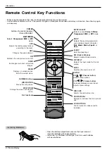
Page 8: ... between ON and STANDBY MULTIMEDIA Selects Component RGB or DVI mode APC Adjusts the factory preset picture according to the room ARC Changes the picture format PIP Switches the sub picture on and off SWAP Exchanges main and sub picture images MENU Displays on screen menus Exits the current menu ENTER CH D D E E Channel button Selects menu options VOL F F G G Volume button Increases decreases soun...

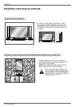
Page 9: ...s on a wall or on a desktop etc The plasma display is designed to be mounted horizontally or vertically The speakers depicted are optional GROUNDING Ensure that you connect the grounding earth wire to prevent possible electric shock If grounding methods are not possible have a qualified electrician install a separate circuit breaker Do not try to ground the unit by connecting it to telephone wires...

Page 10: ...de position When installing the monitor vertically you have to change the OSD On Screen Display display mode so that the menus will appear correctly and also to protect the monitor from overheating Refer to P 20 Desktop Pedestal Installation Desktop Pedestal Installation For proper ventilation allow a clearance of 4 on each side and the top 2 36 on the bottom and 2 from the wall Detailed installat...

Page 11: ...s manual 2 Use the INPUT SELECT button on the remote control to select Video If connected to S VIDEO select the S Video external input source VCR Setup VCR Setup After subscribing to a cable TV service from a local provider and installing a converter you can watch cable TV programming The monitor cannot display TV programming unless a TV tuner device or cable TV converter box is connected to the M...

Page 12: ...ipment Refer to external equipment operating guide Component ports of the Monitor Y PB PR Video output ports of DVD player Y Y Y Y Pb B Y Cb PB Pr R Y Cr PR How to connect 1 Connect the DVD video outputs to the COMPONENT Y PB PR INPUT jacks and connect the DVD audio outputs to the AUDIO INPUT jacks on the monitor as shown in the figure 2 If your DVD only has an S Video output jack connect this to ...

Page 13: ...r There may be noise associated with the resolution vertical pattern contrast or brightness in PC mode If noise is present change the PC mode to another resolution change the refresh rate to another rate or adjust the brightness and contrast on the menu until the picture is clear If the refresh rate of the PC graphic card can not be changed change the PC graphic card or consult the manufacturer of...

Page 14: ... 66 72 80 75 00 85 00 60 00 70 00 75 00 60 00 70 00 75 00 35 156 37 879 48 077 46 875 53 674 49 725 48 363 56 476 60 023 54 348 63 995 67 500 68 681 60 000 63 981 56 25 60 31 72 18 75 00 85 06 74 55 60 00 70 06 75 02 60 05 70 01 75 00 75 06 60 00 60 02 Vertical Frequency Hz Resolution 800x600 832x624 1024x768 1152x864 1152x870 1280x1024 Horizontal Frequency KHz Vertical Frequency Hz 1280x960 Monit...

Page 15: ...OFF button on the Monitor and then press the INPUT SELECT button on the Monitor Or on the remote control press POWER INPUT SELECT or MULTIMEDIA to turn the Monitor on The menus can be shown on the screen in the selected language First select your language 1 Press the MENU button and then use D E button to select the SPECIAL menu 2 Press the G button and then use D E button to select Language 3 Pre...

Page 16: ...utomatically changes to User To initialize values reset to default settings select the Normal option When adjusting color temperature options red green or blue manually ACC automatically changes to User 1 Press the MENU button and then use D E button to select the PICTURE menu 2 Press the G button and then use D E button to select ACC 3 Press the G button and then use D E button to select either N...

Page 17: ...ed Flat Music Movie Sports User This function lets you enjoy the best sound without any special adjustment because the Monitor has the appropriate sound option based on the program content When adjusting sound options treble bass and balance manually DASP automatically changes to User AVL maintains an equal sound level even if you change channels 1 Press the MENU button and then use D E button to ...

Page 18: ...timer Auto off TIMER MENU Sleep Sleep T Timer imer The Sleep Timer turns the Monitor off at the preset time Note that this setting is cleared when the monitor is turned off 1 Press the SLEEP button repeatedly to select the number of minutes First the Min option appears on the screen followed by the following sleep timer options 10 20 30 60 90 120 180 and 240 minutes 2 When the number of minutes yo...

Page 19: ...ns OSD Rotate Normal White wash Orbiter Inversion SPECIAL MENU 1 Press the MENU button and then use D E button to select the SPECIAL menu 2 Press the G button and then use D E button to select ISM Method 3 Press the G button and then use D E button to select either Normal White wash Orbiter or Inversion Normal If image sticking is never a problem ISM is not necessary set to Normal White wash White...

Page 20: ...enu 2 Press the G button and then use D E button to select OSD On Screen Display Rotate 3 Press the G button and then use D E button to select Normal or Rotate Select Normal if the monitor was installed horizontally Select Rotate if the monitor was installed vertically 4 Press the ENTER button to save Menu Rotation for V Menu Rotation for Vertical V ertical Viewing MU 42PZ44M 44V 90C 90M 90V serie...

Page 21: ...Picture Format Caution If a 4 3 fixed image is on the screen for a long time it may remain visible Set every aspect ratio for RGB 480p DVI 480p Component 480i 480p Video and S Video sources Use 4 3 or 16 9 for other input sources 1 Use the ARC button repeatedly to select the desired picture format You can also adjust ARC in the SCREEN menu 4 3 Choose 4 3 when you want to view a picture with an ori...

Page 22: ... The Clock adjustment range is 50 50 5 Press the ENTER button to save Phase 0 Clock 0 SCREEN Prev Auto config ARC Zoom in out Position Manual config Screen adj G G Reset YNR SCREEN MENU Screen Screen Adjustments V Adjustments Video S V ideo S Video and Component 480i mode only ideo and Component 480i mode only Use this function to correct jittering or picture instability while viewing a video tape...

Page 23: ...GA ide VGA mode RGB PC DVI PC mode only mode RGB PC DVI PC mode only To see a normal picture match the resolution of RGB mode and selection of VGA mode 1 Press the MENU button and then use D E button to select the SCREEN menu 2 Press the G button and then use D E button to select VGA Mode 3 Press the G button and then use D E button to select the desired VGA resolution 4 Press the ENTER button to ...

Page 24: ... picture moves up down left right You can also move the PIP position with Win position in the PIP DW menu Swapping the PIP Swapping the PIP Press the SWAP button to exchange the main and sub pic tures Selecting an Input Signal Source for the PIP Selecting an Input Signal Source for the PIP Use the PIP INPUT button to select the input source for the sub picture Main Picture Sub Picture 10 30 10 30 ...

Page 25: ... Window mode main and sub picture sizes are changed simultaneously Using the Win size function in PIP mode sub picture size is changed Win position is not functional in Double Window mode Swapping the Double W Swapping the Double Window indow Use the SWAP button to switch the main and sub pictures in Double Window mode DW 1 DW 2 10 30 10 30 Component Video Video Component Win size F F G G Main Pic...

Page 26: ... to an external control device such as a computer or an A V control system and control the Monitor s functions externally Connect the serial port of the control device to the RS 232C jack on the Monitor back panel RS 232C connection cables are not supplied with the Monitor T Type of Connector D Sub 9 Pin Male ype of Connector D Sub 9 Pin Male RS 232C Configurations RS 232C Configurations External ...

Page 27: ...ving Protocol ransmission Receiving Protocol OK Acknowledgement The Monitor transmits ACK acknowledgement based on this format when receiving normal data At this time if the data is data read mode it indicates present status data If the data is data write mode it returns the data of the PC computer Command2 Set ID OK Data x Error Acknowledgement The Monitor transmits ACK acknowledgement based on t...

Page 28: ...ion Data 0 Volume mute on Volume off 1 Volume mute off Volume on k e Set ID Data Cr Acknowledgement e Set ID OK Data x 03 Aspect Ratio Command2 c Main picture format G To adjust the screen format You can also adjust the screen format using the ARC Aspect Ratio Control button on remote control or in the Screen menu Transmission Data 0 Wide screen 16 9 1 Normal screen 4 3 2 Full screen Zoom 3 Horizo...

Page 29: ...icture DW Double Window You can also control the PIP DW using the PIP or DW but ton on the remote control or in the PIP DW menu Transmission Data 0 PIP DW off 1 PIP 2 DW1 3 DW2 k n Set ID Data Cr Acknowledgement n Set ID OK Data x G To adjust the screen sharpness You can also adjust sharpness in the Picture menu Transmission 11 Sharpness Command2 k Data Min 0 Max 64 Refer to Real data mapping 1 Se...

Page 30: ...K Data x 20 Balance Command2 t G To adjust balance You can also adjust balance in the Sound menu Transmission Data Min 0 Max 64 Refer to Real data mapping 1 See page 28 k t Set ID Data Cr Acknowledgement t Set ID OK Data x 18 Treble Command2 r G To adjust treble You can also adjust treble in the Sound menu Transmission Data Min 0 Max 64 Refer to Real data mapping 1 See page 28 k r Set ID Data Cr A...

Page 31: ...ssion Data Min 0 Max 64 Refer to Real data mapping 1 See page 28 j t Set ID Data Cr Acknowledgement t Set ID OK Data x 32 Auto Configure Command2 u G To adjust picture position and minimize image shaking automatically It works only in RGB PC mode Transmission Data 1 To set j u Set ID Data Cr Acknowledgement u Set ID OK Data x 25 PIP Input Select Command2 y G To select input source for sub picture ...

Page 32: ...a code TC Tf T1 C0 Carrier frequency FCAR 1 TC fOSC 12 Duty ratio T1 TC 1 3 Repeat frame C1 C2 C3 C4 C5 C6 C7 C0 C1 C2 C3 C4 C5 C6 C7 D0 D1 D2 D3 D4 D5 D6 D7 D0 D1 D2 D3 D4 D5 D6 D7 Repeat code 9 ms 4 5 ms 0 55 ms 9 ms 2 25 ms G Bit description G Frame interval Tf The waveform is transmitted as long as a key is depressed Bit 0 Tf Tf Tf 108ms 455KHz 0 56 ms 0 56 ms 1 12 ms Bit 1 2 24 ms How to Conn...

Page 33: ...Selection Discrete IR Code Input Video Selection Discrete IR Code Input S video Selection R C Button R C Button R C Button R C Button R C Button R C Button R C Button R C Button PIP Double window Exchange R C Button 4 3 16 9 R C Button R C Button R C Button R C Button R C Button R C Button R C Button 4 3 16 9 Zoom mode Selection Discrete Only 4 3 mode Discrete Only 16 9 mode Discrete Only Zoom mod...

Page 34: ...nt distance between the Monitor and the VCR Activate any function to restore the brightness of the picture If still picture is on the screen for more than 5 minutes the screen gets dark The remote control doesn t work Check to see if there is any object between the Plasma Display and the remote control causing obstruction Are batteries installed with correct polarity to to Refer to p 8 Install new...

Page 35: ...he cabinet with a soft dry lint free cloth Please be sure not to use a wet cloth If you expect to leave your Monitor dormant for a long time such as a vacation it s a good idea to unplug the power cord to protect against possible damage from lightning or power surges Early malfunctions can be prevented Careful and regular cleaning can extend the amount of time you will have your new Monitor Be sur...

Page 36: ...t Resolution Color Operating Temperature Range Operating Humidity Range Maximum Elevation MU 42PZ44 44A 44B 44K 44R 44S MU 42PZ44M 44MA 44MB 44MK 44MR 44MS MU 42PZ44V 44VA 44VB 44VK 44VR 44VS MU 42PZ90 90A 90B 90K 90R 90S MU 42PZ90M 90MA 90MB 90MK 90MR 90MS MU 42PZ90V 90VA 90VB 90VK 90VR 90VS MU 42PZ90C 40 7 1033 24 5 622 3 2 81 75 34 AC100 240V 50 60Hz 852 x 480 Dot 16 770 000 256 steps of each R...

Page 37: ...Owner s Manual 37 Notes Notes Notes ...

Page 38: ...38 Plasma Display Notes Notes Notes ...

Page 39: ...Owner s Manual 39 Notes Notes Notes ...

Reviews: