background image

3

Important safeguards for you and your new product

Your product has been manufactured and tested with your safety in mind. However, improper use can result in potential electrical
shock or fire hazards. To avoid defeating the safeguards that have been built into your new product, please read and observe the
following safety points when installing and using your new product, and save them for future reference.

Observing the simple precautions discussed in this booklet can help you get many years of enjoyment and safe operation that are
built into your new product.

This product complies with all applicable U.S. Federal safety requirements, and those of the Canadian Standards Association.

1. Read Instructions
All the safety and operating instructions should be read before
the product is operated.
2. Follow Instructions
All operating and use instructions should be followed.
3. Retain Instructions
The safety and operating instructions should be retained for
future reference.
4. Heed Warnings
All warnings on the product and in the operating instructions
should be adhered to.
5. Cleaning
Unplug this product from the wall outlet before cleaning. Do not
use liquid cleaners or aerosol cleaners. Use a damp cloth for
cleaning.
6. Water and Moisture
Do not use this product near water, for example, near a bath tub,
wash bowl, kitchen sink, or laundry tub, in a wet basement, or
near a swimming pool.
7. Accessories Carts and Stands
Do not place this product on a slippery or tilted surface, or on an
unstable cart, stand, tripod, bracket, or table. The product may
slide or fall, causing serious injury to a child or adult, and serious
damage to the product. Use only with a cart, stand, tripod, brack-
et, or table recommended by the manufacturer, or sold with the
product. Any mounting of the product should follow the manu-
facturer’s instructions, and should use a mounting accessory
recommended by the manufacturer.
8. Transporting Product
A product and cart combination should be moved with care.
Quick stops, excessive force, and uneven surfaces may cause
the product and cart combination to overturn.

9. Attachments
Do not use attachments not recommended by the product man-
ufacturer as they may cause hazards.
10. Ventilation
Slots and openings in the cabinet are provided for ventilation
and to ensure reliable operation of the product and to protect it
from overheating, and these openings must not be blocked or
covered. The openings should never be blocked by placing the
product on a bed, sofa, rug, or other similar surface. This prod-
uct should not be placed in a built-in installation such as a book-

case or rack unless proper ventilation is provided or the manu-
facturer’s instructions have been adhered to.
11. Power Sources
This product should be operated only from the type of power
source indicated on the marking label. If you are not sure of the
type of power supply to your home, consult your product dealer
or local power company. For products intended to operate from
battery power, or other sources, refer to the operating instruc-
tions.
12. Power-Cord Polarization
This product is equipped with a three-wire grounding type plug,
a plug having a third (grounding) pin. This plug will only fit into
the grounding-type power outlet. This is a safety feature. If you
are unable to insert the plug into the outlet, contact your electri-
cian to replace your obsolete outlet. Do not defeat the safety pur-
pose of the grounding-type plug.
13. Power-Cord Protection
Power-supply cords should be routed so that they are not likely
to be walked on or pinched by items placed upon or against
them, paying particular attention to cords at plugs, convenience
receptacles, and the point where they exit from the product.
14. Outdoor Antenna Grounding
If an outside antenna or cable system is connected to the prod-
uct, be sure the antenna or cable system is grounded so as to
provide some protection against voltage surges and built-up sta-
tic charges. Article 810 of the National Electrical Code (U.S.A.),
ANSI/ NFPA 70 provides information with regard to proper
grounding of the mast and supporting structure, grounding of the
lead-in wire to an antenna discharge unit, size of grounding con-
ductors, location of antenna-discharge unit, connection to
grounding electrodes, and requirements for the grounding elec-
trode. 

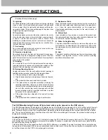
PORTABLE CART WARNING

(Continued on next page)

SAFETY INSTRUCTIONS

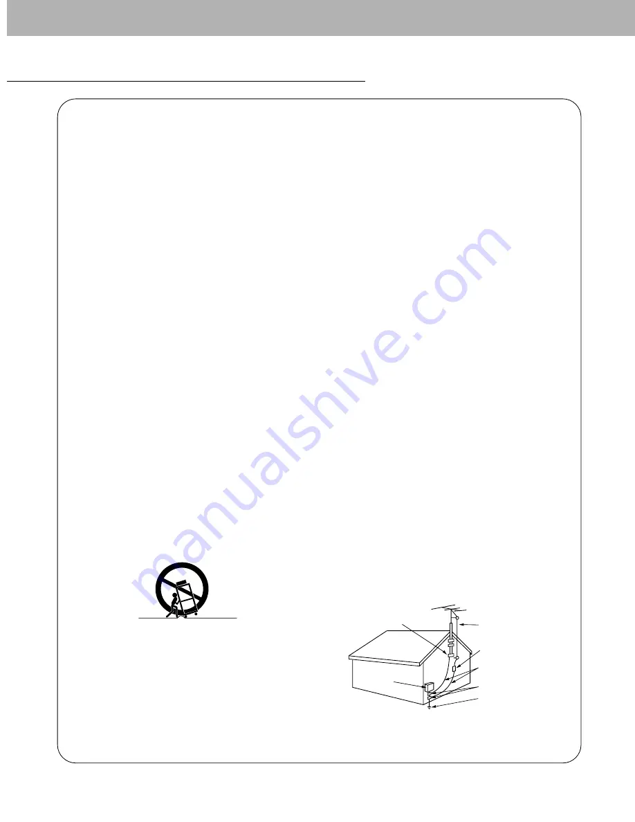
Antenna Lead in Wire

Antenna Discharge Unit
(NEC Section 810-20)

Grounding Conductor
(NEC Section 810-21)

Ground Clamps

Power Service Grounding
Electrode System (NEC
Art 250, Part H)

Ground Clamp

Electric Service

Equipment

Example of Grounding According to National
Electrical Code Instructions

NEC - National Electrical Code

Summary of Contents for MU-42PZ40

Page 1: ...ure reference cord model number and serial number of the Monitor e the label attached on the back of the Monitor and quote information to your dealer when you require service del number ial number ODELS MU 42PZ40 41 MU 42PZ40A 41A MU 42PZ40B 41B MU 42PZ40K 41K MU 42PZ40R 41R MU 42PZ40S 41S O 3828VA0361A RF02RA ...

Page 2: ...ainst harmful interference in a residential installation This equipment generates uses and can radiate radio frequency energy and if not installed and used in accordance with the instructions may cause harmful interference to radio communications However there is no guarantee that interference will not occur in a particular instal lation If this equipment does cause harmful interference to radio o...

Page 3: ...cabinet are provided for ventilation and to ensure reliable operation of the product and to protect it from overheating and these openings must not be blocked or covered The openings should never be blocked by placing the product on a bed sofa rug or other similar surface This prod uct should not be placed in a built in installation such as a book case or rack unless proper ventilation is provided...

Page 4: ...damaged f If the product exhibits a distinct change in performance 21 Replacement Parts When replacement parts are required be sure the service tech nician has used replacement parts specified by the manufactur er or have the same characteristics as the original part Unauthorized substitutions may result in fire electric shock or other hazards 22 Safety Check Upon completion of any service or repa...

Page 5: ... 16 White Wash 16 Key Lock 16 Adjusting Auto Color Control 17 Manual Color Temperature Control 17 Sleep Timer 17 Screen Menu Options Auto Adjustment 18 Adjusting Horizontal Vertical Position 18 Picture Phase Adjustments 18 Initializing 18 Selecting Wide VGA mode 19 Screen Adjustments 19 Screen Noise Reduction 19 Setting Picture Format 20 Split Zoom 20 Picture Size Adjustment 20 Enlarged Picture Po...

Page 6: ...information refer to Speaker Speaker Stand manual 2 RS 232C INPUT CONTROL SERVICE PORT Connect to the RS 232C port on a PC 3 AUDIO INPUT RGB1 INPUT PC DTV INPUT RGB2 INPUT DIGITAL RGB INPUT JACKS Connect the monitor output socket of the PC to this socket 4 RGB1 OUTPUT PC DTV OUTPUT JACKS You can watch the RGB1 signal on another monitor connect RGB1 OUTPUT PC DTV OUTPUT to another monitor s PC inpu...

Page 7: ...GB INPUT RGB1 INPUT PC DTV INPUT RGB1 OUTPUT PC DTV OUTPUT COMPONENT DVD DTV INPUT RS 232C INPUT CONTROL SERVICE EXTERNAL SPEAKER LOCK CONTROL ON OFF Y PB PR MONO R AUDIO L R AUDIO L S VIDEO VIDEO INPUT AC INPUT AUDIO INPUT AUDIO INPUT AUDIO INPUT AUDIO INPUT VIDEO INPUT COMPONENT DVD DTV INPUT S VIDEO INPUT COMPONENT AUDIO INPUT Monitor External Equipment Connection Panel RS 232C INPUT RGB2 INPUT...

Page 8: ...erate the corresponding external equipment See external equipment operating guide After subscribing to a cable TV service from a local provider and installing a converter you can watch cable TV program ming This monitor cannot display TV programming unless a TV tuner device or cable TV converter box is connected to the Monitor For further information regarding cable TV service contact your local c...

Page 9: ...L RGB INPUT port on the Monitor Connect the audio cable from the PC to the Audio input on the Monitor Audio cables are not included with the Monitor If using a sound card adjust PC sound as required This monitor apply a VESA Plug and Play Solution The monitor provides EDID data to the PC system with a DDC proto col The PC adjusts automatically to use this monitor DDC protocol is preset for RGB1 An...

Page 10: ...152x864 1152x870 1280x960 1280x1024 Horizontal Frequency KHz Vertical Frequency Hz RGB2 Mode Monitor Display Specifications Monitor Display Specifications Resolution 640x350 640x400 640x480 800x600 Horizontal Frequency KHz 31 468 37 861 31 469 37 927 31 469 35 000 37 861 37 500 43 269 45 913 53 011 64 062 35 156 37 879 48 077 46 875 53 674 56 000 64 016 70 09 85 08 70 08 85 03 59 94 66 66 72 80 75...

Page 11: ... format Refer to p 20 ZOOM Reduces the main picture size Refer to p 20 SPLIT ZOOM Enlarge the screen with regular ration Refer to p 20 MENU Displays on screen menus one by one Exits the current menu Memorizes menu changes NUMBER buttons PIP Switches the sub picture on and off Refer to p 21 TWIN PICTURE Refer to p 22 PIP INPUT Selects the input mode for the sub picture Refer to p 21 22 SOUND SELECT...

Page 12: ...SELECT PIP INPUT VOL KEY LOCK Remote Control DVI Cable Accessories 2 inches 4 inches 2 36 inches 4 inches 4 inches 4 inches 4 inches 4 inches 4 inches 2 inches To Mount on a Wall Wall mount minimum allowable clearances for adequate ventilation To Install on a Desktop Pedestal mount minimum allowable clearances for adequate ventilation Wall Mount Installation Desktop Pedestal Installation The monit...

Page 13: ...he Monitor was turned off with the remote control and the ON OFF button on the Monitor Press the ON OFF button on the Monitor and then press the INPUT SELECT button on the Monitor or press the POWER INPUT SELECT button on the remote control to turn the Monitor on Menu Language Selection The menus can be shown on the screen in the selected language First select your language 1 Press the MENU button...

Page 14: ...the MENU button 1 Press the APC button to select the picture appearance setup option APC Auto Picture Control APC Auto Picture Control Manual Picture Control User option Manual Picture Control User option Each press of the APC button changes the screen display as shown below You can also select CLEAR SOFT or USER in the PICTURE menu Picture options CLEAR and SOFT are preset and programmed for good...

Page 15: ...ct FLAT SPORTS CINEMA MUSIC or USER in the SOUND menu FLAT SPORTS CINEMA MUSIC USER This function lets you enjoy the best sound without any special adjustment because the Monitor automatically selects the appropriate sound option based on the program content This feature maintains an equal volume level even if you change channels 1 Press the MENU button and then use D E button to select the SOUND ...

Page 16: ...unction perfectly 1 Press the MENU button and then use D E button to select the SPECIAL menu 2 Press the G button and then use D E button to select WHITE WASH 3 Press the G button and then use D E button to select ON or OFF When you select ON the screen changes to white 4 Press the MENU button Special Menu Options LANGUAGE KEY LOCK ORBITER G WHITE WASH COLOR TEMP SET ID SPECIAL ON OFF LANGUAGE KEY...

Page 17: ...appropriate adjustments 5 Press the MENU button The adjustment range of RED GREEN and BLUE is 10 10 Manual Color Manual Color T Temperature Control User option emperature Control User option LANGUAGE KEY LOCK ORBITER WHITE WASH COLOR TEMP G SET ID SPECIAL TO SET ACC G RED GREEN BLUE COLOR TEMP NORMAL COOL WARM USER LANGUAGE KEY LOCK ORBITER WHITE WASH COLOR TEMP G SET ID SPECIAL TO SET a To check ...

Page 18: ...ting Horizontal Vertical Position ertical Position 1 Press the MENU button and then use D E button to select the SCREEN menu 2 Press the G button and then use D E button to select SCREEN ADJ 3 Press the G button and then use D E button to select V POSITION or H POSITION 4 Press the G button and then use the F G button to adjust until you get desired hori zontal or vertical position The adjustment ...

Page 19: ...icture noise which may appear on the screen during watching the TV in a weak signal area 1 Press the MENU button and then use D E button to select the SCREEN menu 2 Press the G button and then use D E button to select SCREEN ADJ 3 Press the G button and then use D E button to select TV or VCR Select the VCR option if watching a VCR Select the TV option for other equipment Except VCR 4 Press the ME...

Page 20: ...COMPONENT If 4 3 is on the screen for a long time that fixed image may remain visible 1 Press the ARC button to select a desired picture format Each press of ARC button or F G button changes the screen display as shown below You can also select 16 9 4 3 or ZOOM in the SCREEN menu ARC F G 16 9 ARC F G 4 3 ARC F G ZOOM Split Zoom Split Zoom This is the function to enlarge the screen with regular rat...

Page 21: ...t Signal Source for the PIP Selecting a Input Signal Source for the PIP Press the PIP INPUT button to select the input source for the sub picture Each press of PIP INPUT button or F G button changes the screen display as shown below In RGB1 PC and RGB2 PC for main picture you can select RGB1 DTV COMPONENT VIDEO and S VIDEO for sub picture PIP INPUT F G VIDEO Using Sub picture Still Function Using ...

Page 22: ...E button cycles through the screen displays shown below Selecting a Input Signal Source for the Selecting a Input Signal Source for the T Twin Picture win Picture Press the PIP INPUT button to select the input source for the sub picture Each press of PIP INPUT button or F G button changes the screen display as shown below In RGB1 PC and RGB2 PC for main picture you can select RGB1 DTV COMPONENT VI...

Page 23: ... D Sub 9 Control line 3 2 5 6 4 8 7 PDP D Sub 9 2 3 5 4 6 7 8 RXD TXD GND DTR DSR RTS CTS TXD RXD GND DTR DSR RTS CTS PC 3 wire configuration Not standard D Sub 9 3 2 5 4 6 7 8 PDP D Sub 9 External Control Device Setup Connect the RS 232C input jack to an external control device such as a computer or an A V control system and control the Monitor s functions externally Connect the serial port of th...

Page 24: ...stment k v 0 64 22 Green adjustment k w 0 64 23 Blue adjustment k 0 64 24 PIP input source k y 0 3 25 Orbiter j p 0 1 26 White Wash j q 0 1 COMMAND 1 COMMAND 2 DATA Hexadecimal The Monitor transmits ACK acknowledgement based on this format when receiving normal data At this time if the data is data read mode it indicates present status data If the data is data write mode it returns the data of the...

Page 25: ...2 Full screen Zoom k c Set ID Data Cr Acknowledgement Data 0 Wide screen 16 9 1 Normal screen 4 3 2 Full screen Zoom Using the PC input you select either 16 9 or 4 3 screen aspect ratio c Set ID OK Data x 04 Screen Mute Command2 d G To select screen mute on off Transmission Data 0 Screen mute off Picture on 1 Screen mute on Picture off k d Set ID Data Cr Acknowledgement d Set ID OK Data x 06 Volum...

Page 26: ...te control or in the screen menu Transmission Data 0 PIP DW off 1 PIP S 2 DW1 3 DW2 4 PIP L k n Set ID Data Cr Acknowledgement n Set ID OK Data x G To adjust the screen sharpness You can also adjust sharpness in the picture menu Transmission 11 Sharpness Command2 k Data Min 0 Max 64 Refer to Real data mapping1 as shown below k k Set ID Data Cr Acknowledgement k Set ID OK Data x 12 OSD Select Comma...

Page 27: ...erature Transmission Data Min 0 Max 64 Refer to Real data mapping 2 See page 26 Data Min 0 Max 64 k Set ID Data Cr Acknowledgement Set ID OK Data x 24 PIP Input Select Command2 y G To select input source for sub picture in PIP mode Transmission Data 0 RGB1 DTV 1 COMPONENT 2 VIDEO 3 S VIDEO k y Set ID Data Cr Acknowledgement y Set ID OK Data x 20 Color Temperature Command2 u G To adjust color tempe...

Page 28: ...igh custom code Data code Data code TC Tf T1 C0 Carrier frequency FCAR 1 TC fOSC 12 Duty ratio T1 TC 1 3 Repeat frame C1 C2 C3 C4 C5 C6 C7 C0 C1 C2 C3 C4 C5 C6 C7 D0 D1 D2 D3 D4 D5 D6 D7 D0 D1 D2 D3 D4 D5 D6 D7 Repeat code 9 ms 4 5 ms 0 55 ms 9 ms 2 25 ms G Bit description G Frame interval Tf The waveform is transmitted as long as a key is depressed Bit 0 Tf Tf Tf 108ms 455KHz 0 56 ms 0 56 ms 1 12...

Page 29: ...FH 92H R C Button R C Button R C Button R C Button R C Button Power On Off Discrete IR Code Only Power On Discrete IR Code Only Power Off R C Button R C Button R C Button R C Button R C Button R C Button R C Button R C Button R C Button R C Button R C Button R C Button Discrete IR Code Input RGB1 Selection Discrete Input RGB2 Selection Discrete Input VIDEO Selection Discrete Input S VIDEO Selectio...

Page 30: ... or Poor picture Select COLOR in the VIDEO menu and press the VOLUME G button Refer to p 14 Keep a certain distance between the Monitor and the VCR Activate any function to restore the brightness of the picture If still picture is on the screen for more than 5 minutes the screen gets dark The remote control doesn t work Check to see if there is any object between the Plasma Display and the remote ...

Page 31: ...nt Wring the cloth until it s almost dry and then use it to wipe the screen 2 Make sure the excess water is off the screen and then let it air dry before you turn on your Monitor To remove dirt or dust wipe the cabinet with a soft dry lint free cloth Please be sure not to use a wet cloth If you leave your Monitor dormant for a long time such as a vacation it s a good idea to unplug the power cord ...

Page 32: ......

Reviews: