11
ENGLISH
Refrigerant piping on three principles
Drying Cleanliness
Airtight
Should be no moisture
inside
No dust inside.
There is no refrigerant
leakage
Items
Moisture
Dust
Leakage
Cause
failure
- Significant hydroly-
sis of refrigerant oil
- Degradation of re-
frigerant oil
- Poor insula’tion of
the compressor
- Do not cold and
warm
- Clogging of EEV,
Capillary
- Degradation of re-
frigerant oil
- Poor insulation of
the compressor
- Do not cold and
warm
- Clogging of EEV,
Capillary
- Gas shortages
- Degradation of re-
frigerant oil
- Poor insulation of
the compressor
- Do not cold and
warm
Coun-
termea-
sure
- No moisture in the pipe
- Until the connec-
tion is completed,
the plumbing pipe
entrance should be
strictly controlled.
- Stop plumbing at
rainy day.
- Pipe entrance
should be taken
side or bottom.
- When removal burr
after cutting pipe, pipe
entrance should be
taken down.
- Pipe entrance
should be fitted cap
when pass through
the walls.
- No dust in the pipe.
- Until the connec-
tion is completed,
the plumbing pipe
entrance should be
strictly controlled.
- Pipe entrance
should be taken
side or bottom.
- When removal burr
after cutting pipe,
pipe entrance
should be taken
down.
- Pipe entrance
should be fitted cap
when pass through
the walls.
- Airtightness test
should be.
- Brazing operations
to comply with
standards.
- Flare to comply
with standards.
- Flange connections
to comply with
standards.
Nitrogen substitution method
Welding, as when heating without nitrogen substitution a large
amount of the oxide film is formed on the internal piping.
The oxide film is a caused by clogging EEV, Capillary, oil hole of accu-
mulator and suction hole of oil pump in compressor.
It prevents normal operation of the compressor.
In order to avoid this problem, Welding should be done after replacing
air by nitrogen gas.
When welding plumbing pipe, the work is required.
Regulator
Nitrogen gas
Pressure 0.02MPa less
Auxiliary valve
Taping
(Should not
contain air)
Welding Point
Note) should not block the outlet side.
When the internal pressure in pipe is abo
ve the atmospheric pressure, pinhole is o
ccurred and it is a leakage cause.
Oxide scale
Nitrogen
1 Always use the nitrogen.(not use oxygen, carbon dioxide, and a
Chevron gas): Please use the following nitrogen pressure
0.02MPa Oxygen – Promotes oxidative degradation of refrigerant
oil. Because it is flammable, it is strictly prohibited to use Carbon
dioxide – Degrade the drying characteristics of gas Chevron
Gas – Toxic gas occurs when exposed to direct flame.
2 Always use a pressure reducing valve.
3 Please do not use commercially available antioxidant.
The residual material seems to be the oxide scale is ob-
served. In fact, due to the organic acids generated by oxida-
tion of the alcohol contained in the anti-oxidants, ants nest
corrosion occurs. (causes of organic acid
’
a copper
+ water + temperature)
CAUTION
!
Cautions in pipe connection/valve operation
WARNING
After completing work, securely tighten both service ports and
caps so that gas does not leak.
!
WARNING
Always use extreme care to prevent the refrigerant gas (R410A)
from leakage while using fire or flame. If the refrigerant gas
comes in contact with the flame from any source, such as a gas
stove, it breaks down and generates a poisonous gas which can
cause gas poisoning. Never perform brazing in an unventilated
room. Always conduct an inspection for gas leakage after installa-
tion of the refrigerant piping has been completed.
!
REFRIGERANT PIPING INSTALLATION
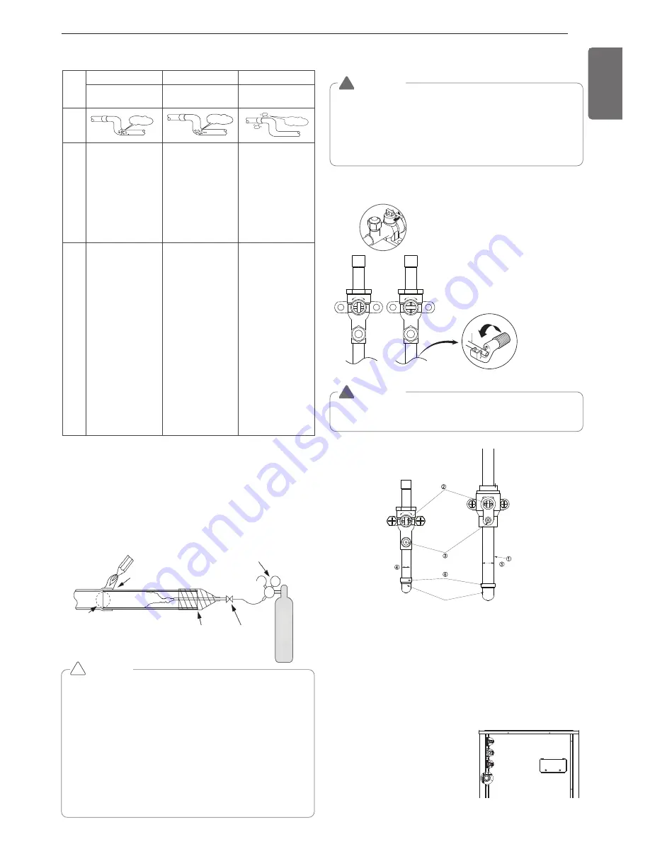
Open status when both the pipe and the valve are
in a straight line.
Cut both the pipe and the valve with a cutter to
suit the length
(Don't cut the length of less than 70mm)
CLOSE
OPEN
h
Remove the front panel before pipe
connection
h
Must check the pipe (liquid pipe, gas
pipe, high/low pressure common
pipe) before pipe connection
①
Pipe joint (auxiliary parts): Securely perform brazing with a nitrogen
blow into the service valve port.(Releasing pressure : 0.02 MPa or
less)
②
Cap: Remove caps and operate valve, etc. After operation, always
reattach caps (tightening torque of valve cap: 25Nm (250kg-cm) or
more). (Don't remove the internal part of the port)
③
Service port: Make the refrigerant pipe vacuum and charge it using
the service port. Always reattach caps after completing work (tight-
ening torque of service cap: 14Nm (140kg-cm) or more).
④
Liquid pipe
⑤
Gas pipe
⑥
Elbow joint (field supply)
Liquid pipe
Gas pipe
High/Low pressure
common pipe
Elbow
Ball Valve(Gas Pipe)
Ball Valve
(Liquid Pipe)
Liquid pipe
Gas pipe
High/Low pressure
common pipe
Liquid pipe
Gas pipe
High/Low pressure
common pipe
Summary of Contents for Multi V ARWN Series
Page 37: ......


