24
ENGLISH
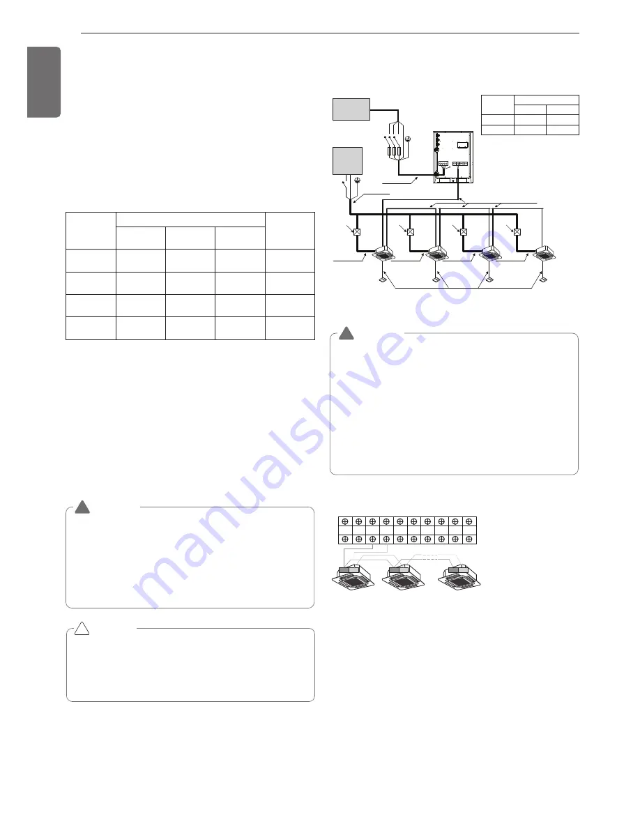
Wiring of main power supply and equipment
capacity
- Use a separate power supply for the Outside Unit and Indoor Unit.
- Bear in mind ambient conditions (ambient temperature,direct sun-
light, rain water,etc.) when proceeding with the wiring and connec-
tions.
- The cable size is the minimum value for metal conduit wiring. The
power cord size should be 1 rank thicker taking into account the line
voltage drops. Make sure the power-supply voltage does not drop
more than 10%.
- Specific wiring requirements should adhere to the wiring regulations
of the region.
- Don't install an individual switch or electrical outlet to disconnect
each of indoor unit separately from the power supply.
Ground wire
1
The power wire Between the master outside unit and slave1 out-
side unit - minimum : 6 mm
2
2
The power wire Between the slave1 outside unit and slave2 out-
side unit - minimum : 4 mm
2
3
The power wire Between the slave2 outside unit and slave3 out-
side unit - minimum : 2.5 mm
2
h
Power supply cords of appliances for outside unit use shall not be
lighter than polychloroprene sheathed flexible cord
(code designation 60245 IEC 57).
h
Please use the 3-phase 4-wire quadrupole Leakage circuit breaker of
circuit breaker.
CAUTION
• Some installation site may require attachment of an earth leakage
breaker. If no earth leakage breaker is installed, it may cause an
electric shock.
• Do not use anything other than breaker and fuse with correct ca-
pacity. Using fuse and wire or copper wire with too large capacity
may cause a malfunction of unit or fire.
!
WARNING
• Follow ordinance of your governmental organization for techni-
cal standard related to electrical equipment, wiring regulations
and guidance of each electric power company.
• Make sure to use specified cables for connections so that no
external force is imparted to terminal connections. If connec-
tions are not fixed firmly, it may cause heating or fire.
• Make sure to use the appropriate type of overcurrent protection
switch. Note that generated overcurrent may include some
amount of direct current.
!
Field Wiring
Single outside unit
R S T N
Switch
Fuse
L
N
Communication cable
(2 Wires Cable)
Power cable
(4 Wires Cable)
Communication cable
(3 Wires Cable)
Power cable
(2 Wires Cable)
Power cable
(2 Wires Cable)
Power cable
(2 Wires Cable)
Power cable
(2 Wires Cable)
Power cable
(2 Wires Cable)
[Outside Unit]
[Indoor Units]
Outside
Power supply
(3Ø 4wires)
Indoor
Power supply
(1
Ø
2wires)
(Main Switch)
Pull Box
(Installer option)
Pull Box
(Installer option)
Pull Box
(Installer option)
Pull Box
(Installer option)
Frequency
Voltage range(V)
Outside
Indoor
60Hz
380V
220V
50Hz
380-415V 220-240V
Master
Outside unit
SODU. B SODU. A
IDU. B
IDU. A
CEN. B
CEN. A
DRY1
DRY2
GND
12V
3
4
3
4
3
4
[Heat Pump]
Between Indoor and Master Outside unit
The GND terminal at the
main PCB is a ‘-’ terminal
for day contact, it is not
the point to make ground
connection.
WARNING
• Indoor Unit ground wires are required for preventing electrical
shock accident during current leakage, Communication disorder by
noise effect and motor current leakage (without connection to
pipe).
• Don't install an individual switch or electrical outlet to disconnect
each of indoor unit separately from the power supply.
• Install the main switch that can interrupt all the power sources in an
integrated manner because this system consists of the equipment
utilizing the multiple power sources.
• If there exists the possibility of reversed phase, lose phase, mo-
mentary blackout or the power goes on and off while the product is
operating, attach a reversed phase protection circuit locally. Run-
ning the product in reversed phase may break the compressor and
other parts.
!
The thickness of Minimum wire (mm
2
)
Leakage cir-
cuit breaker
(4P ELCB)
Main power
wire
Branch wire Ground wire
1 Unit
2.5~6
-
2.5
Below 30~50A
100mA 0.1sec
2 Unit
10~16
-
2.5
Below 75~100A
100mA 0.1sec
3 Unit
25~35
-
4
Below 125~150A
100mA 0.1sec
4 Unit
70
-
6
Below 175~200A
100mA 0.1sec
Summary of Contents for Multi V ARWN Series
Page 37: ......


