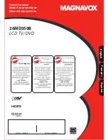
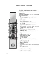
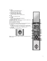
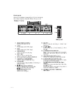
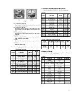
ON/OFF
STOP
PLAY
OPEN/
CLOSE
STOP/
EJECT
PLAY
REC/ITR
DVD
TRK
COPY
VCR
REC
PM
TV
Triple Combi TV
SERVICE MANUAL
CAUTION
BEFORE SERVICING THE CHASSIS,
READ THE SAFETY PRECAUTIONS IN THIS MANUAL.
CHASSIS : MV-033A
MODEL :
Multiplex 72
website:http://biz.LGservice.com
e-mail:http://www.LGEservice.com/techsup.html
SERVICE MANUAL
MODEL : Multiplex 72
LG Electronics inc.
Summary of Contents for Multiplex 72
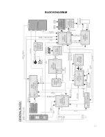
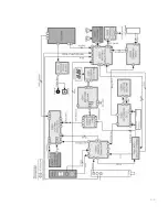
Page 11: ...3 7 BLOCK DIAGRAM ...
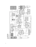
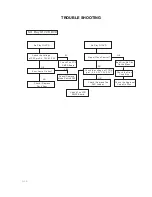
Page 12: ...3 8 ...
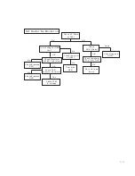
Page 13: ...3 9 ...