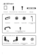
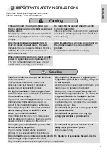
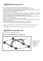
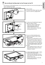
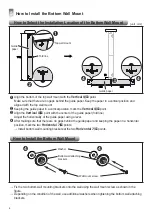
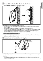
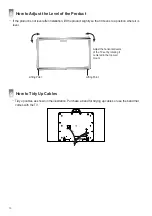
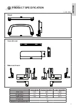
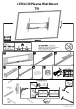
LG OSW200, Install Manual
The LG OSW200 Install Manual is available for download free of charge from our website. This comprehensive manual provides step-by-step instructions to effortlessly set up and install your LG OSW200 product. Obtain the manual today from our website and get started with your new LG OSW200.
Share
Download


Reviews:
No comments
Related manuals for OSW200
M Series
Brand: GCX Pages: 3
M Series
Brand: GCX Pages: 3
E220
Brand: Barkan Pages: 34
E410
Brand: Barkan Pages: 34
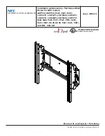
E321
Brand: NEC Pages: 7
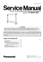
TY-WK5P1SW
Brand: Panasonic Pages: 11

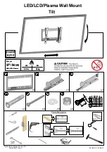
S40
Brand: Barkan Pages: 8

hp2xf-o
Brand: 3idee Pages: 7
PT2
Brand: Rawinternational Pages: 2
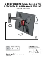
43
Brand: Barkan Pages: 8
E210
Brand: Barkan Pages: 34
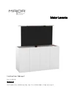
Levante
Brand: MAIOR Pages: 19
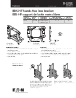
B SERIES
Brand: Eaton Pages: 4
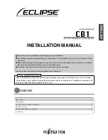
CB1
Brand: Eclipse Pages: 12
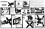
EGMF1
Brand: Echogear Pages: 2
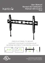
PF400
Brand: Kanto Pages: 16
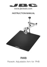
RWB
Brand: jbc Pages: 12
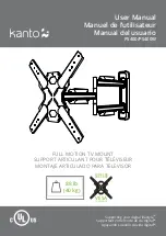
PS400
Brand: Kanto Pages: 16


