83
Remove the following parts in order before replacing this part.
a. Battery Pack(1010) b. Hard Disk Drive(1020) c. PCIE WLAN Card(1030) d. Keyboard(1040)
e. Optical Disk Drive(1050) f. Keyboard Deck(1060) g. Display Module(1070)
■
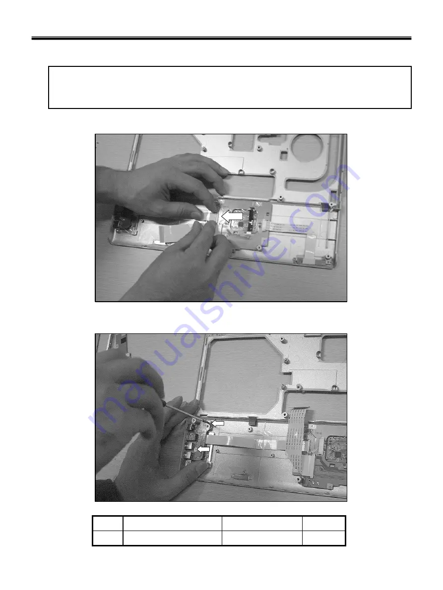
1150 Audio sub board
1. Disconnect the Audio Connector.
2. Remove 2 screws.
2
M2 x L3.0
1SZZBA4041A
1
Qty
Specification
FRU No.
No.
Ch5. Removing and replacing a part
Summary of Contents for P1
Page 2: ...0 Service Manual S1 P1 LG Electronics ...
Page 21: ...19 System Block Diagram Ch3 System information ...
Page 59: ...57 2 Pull the HDD Assy out in the direction shown below Ch5 Removing and replacing a part ...
Page 63: ...61 3 Disconnect the keyboard connector Ch5 Removing and replacing a part ...
Page 65: ...63 Ch5 Removing and replacing a part ...
Page 68: ...66 Ch5 Removing and replacing a part ...
Page 72: ...70 Ch5 Removing and replacing a part ...
Page 77: ...75 4 Remove the Cardbus 5 in 1 Dummy Ch5 Removing and replacing a part ...
Page 79: ...77 Ch5 Removing and replacing a part ...
Page 83: ...81 3 Remove the Main Board Ch5 Removing and replacing a part ...
Page 86: ...84 3 Remove the Audio sub board Ch5 Removing and replacing a part ...
Page 88: ...86 2 Remove the Finger Printer Ch5 Removing and replacing a part ...
Page 90: ...88 2 Remove the Touchpad Ch5 Removing and replacing a part ...
Page 92: ...90 2 Disassemble the LCD Hook located on top of LCD Ch5 Removing and replacing a part ...
Page 97: ...95 Ch5 Removing and replacing a part ...
Page 106: ...Rocky W EXPLODED VIEW 2 NSCRC NBRKH NSCRC NCSNH NHDD1 NLAN1 NCVRC NMEM1 NCVRS ...
Page 113: ...Rocky W EXPLODED VIEW 9 NSCR2 NSCR2 NSCR2 NSCR2 NSUBB NSUBT NSUBF NSUBA NSCR2 ...
Page 118: ...Rocky W EXPLODED VIEW 14 NSCR7 NSCR7 NFAN1 NSCRA NFAN2 NSCR7 NMDM1 NCPU1 NMEM1 ...


