
INSTALLATION MANUAL
AIR
CONDITIONER
Please read this installation manual completely before installing the product.
Installation work must be performed in accordance with the national wiring standards by
authorized personnel only.
Please retain this installation manual for future reference after reading it thoroughly.
[Representative] LG Electronics Inc. EU Representative : LG Electronics
European Shared Service Center B.V. Krijgsman 1, 1186 DM Amstelveen,
The Netherlands
[Manufacturer] LG Electronics Inc. Changwon 2nd factory 84, Wanam-ro,
Seongsan-gu, Changwon-si, Gyeongsangnam-do, KOREA
MFL69940001
Rev.02_020420
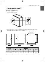
Applied(AHU)
AHU CONTROLLER
Original instruction
www.lg.com
Copyright © 2017 - 2020 LG Electronics Inc. All Rights Reserved.
ENGLISH
IT
ALIANO
ESP
AÑOL
FRANÇAIS
DEUTSCH
POR
TUGUÊS
Summary of Contents for PAHCMR000
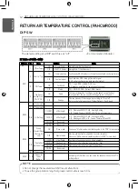
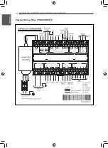
Page 14: ...14 RETURN AIR TEMPERATURE CONTROL PAHCMR000 ENGLISH Electric Wiring Work PAHCMR000 ...
Page 46: ...46 ENGLISH ...
Page 47: ......


