


34
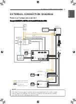
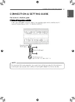
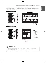
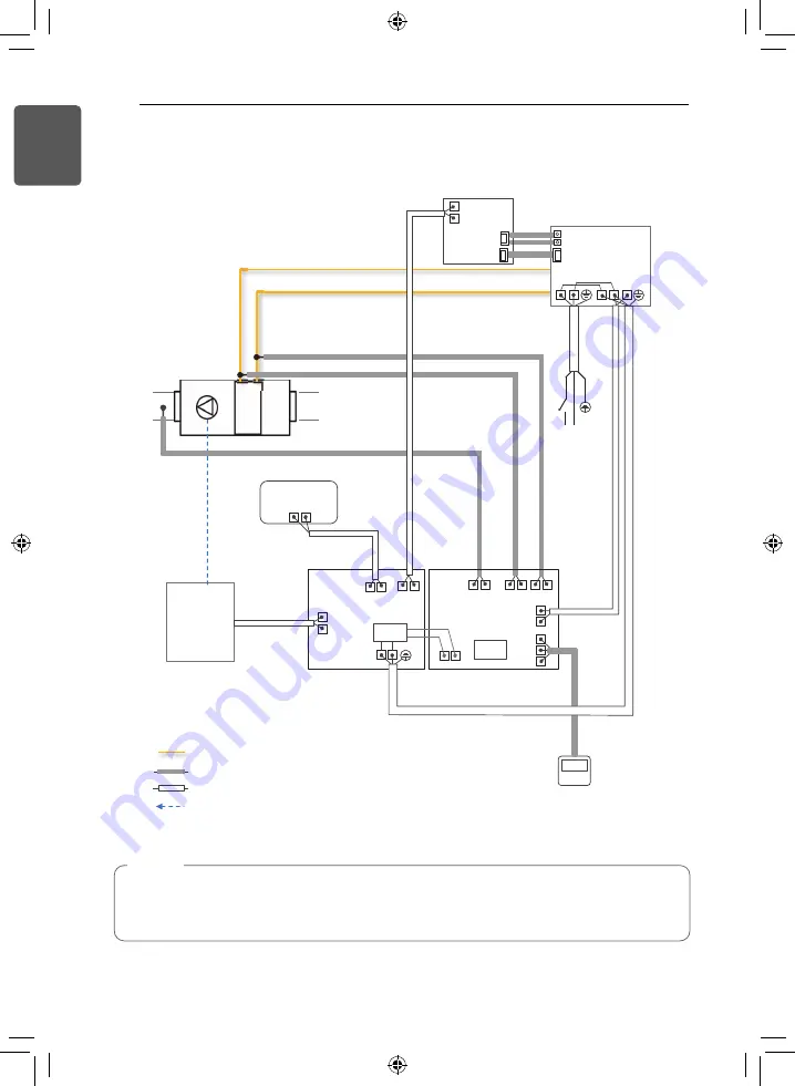
EXTERNAL CONNECTION DIAGRAM
ENGLISH
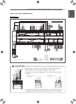
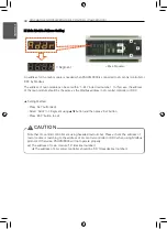
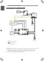
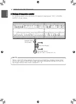
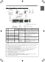
Example 2) Single Split + LG Control/DDC (Modbus RTU)
RI2 G
RI3 G RI4 G
DX
Coil
Pipe out (Gas) Thermistor
Pipe in (Liquid) Thermistor
Fan contro
l
Discharge Thermistor
Main
module
SINGLE N
SINGLE S
GND
12V
SIG
A+ B-
CH2
Comm.
module
EEV
Liquid pipe
Gas pipe
SINGLE SPLIT
Outdoor unit
2(N)
1(L)
2(N)
1(L)
3 (CN_COM)
PI 485
PMNFP14A1
BUS -A
BUS -B
CN_CENTRAL
CN_PWR
CN_OUT
CN_CP(N)
CN_CP(L)
L N
Power Supply
Adapter
L
N
B- CH4
A+ CH4
A+ B-
CH3
A+ B-
ACP : CH5
AC SMART : CH1
Central Controller
Modbus
Communication
Refrigerant Piping (Field Supply)
Wire & Thermistor (LG Supply)
AI/DI/DO Signal(Field Supply)
Wire (Field Supply)
Air Handling Unit
(Field supply)
Local AHU
Controller
(Out of LG scope)
Wired Remote
Controller
NOTE
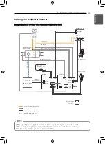
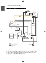
• The type of power supply of outdoor unit can vary depending on the outdoor model.
• Please make wiring between LG controller and outdoor unit with the same polarity.
• LG controller can be optionally applied with DDC.
Summary of Contents for PAHCMR000
Page 14: ...14 RETURN AIR TEMPERATURE CONTROL PAHCMR000 ENGLISH Electric Wiring Work PAHCMR000 ...
Page 46: ...46 ENGLISH ...
Page 47: ......


