20
PRDCAM
AHU Communication Kit Installation Manual
Due to our policy of continuous product innovation, some specifications may change without notification.
©LG Electronics U.S.A., Inc., Englewood Cliffs, NJ. All rights reserved. “LG” is a registered trademark of LG Corp.
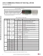
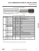
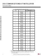
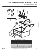
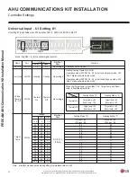
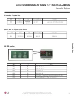
Controller Settings
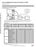
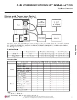
AHU COMMUNICATIONS KIT INSTALLATION
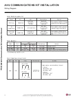
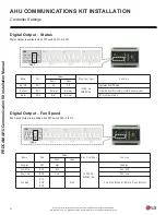
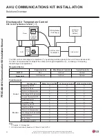
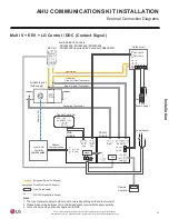
Note : Dip SW 1-2 is for contact signal control
Note : Maintain previous value when getting intermediate value to UI4
Name
Port
Value
Electrical
Spec.
Function
Short
Open
On / Off
UI1 (DI)
On
Off
Non voltage
Operation On/Off Control
Cool / Heat UI2 (DI)
Heating
Cooling
Non voltage
Heating/Cooling Operation Control
if operation mode (DIP SW 3-2, 3-3) is set to cooling only mode, UI2
“Short” status will work as fan mode.
if operation mode (DIP SW 3-2, 3-3) is set to heating only mode, UI2
“Open” status will work as fan mode.
Forced
Thermo
On / Off
UI3 (DI)
Thermal
On
Thermal
Off
Non voltage
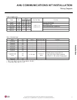
When UI4(Target temp.) is less than 1.5 V, Target temp. and Room
temp. is fixed like below table
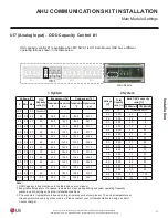
Target
Temp.
UI4 (AI)
Voltage
Electrical
Spec.
Cooling Mode (
°
F)
V
Min.
Max
< 1.5
0
1.6
DC 0~10 V,
20 mA
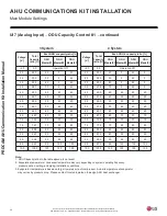
UI3 short : 60
UI3 open : 80
UI3 short : 80
UI3 open : 60
0
6
0
6
1
.
2
9
.
1
0
.
2
2
6
2
6
6
.
2
4
.
2
5
.
2
4
6
4
6
1
.
3
9
.
2
0
.
3
6
6
6
6
6
.
3
4
.
3
5
.
3
8
6
8
6
1
.
4
9
.
3
0
.
4
9
6
9
6
6
.
4
4
.
4
5
.
4
1
7
1
7
1
.
5
9
.
4
0
.
5
3
7
3
7
6
.
5
4
.
5
5
.
5
5
7
5
7
1
.
6
9
.
5
0
.
6
7
7
7
7
6
.
6
4
.
6
5
.
6
8
7
8
7
1
.
7
9
.
6
0
.
7
0
8
0
8
6
.
7
4
.
7
5
.
7
2
8
2
8
1
.
8
9
.
7
0
.
8
4
8
4
8
6
.
8
4
.
8
5
.
8
6
8
6
8
0
.
0
1
7
.
8
≤
0
.
9
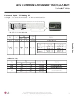
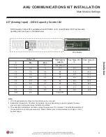
Mode
UI3 status
Thermal On
Target temp. = 60
Room temp. = 80
Target temp. = 80
Room temp. = 60
Thermal Off
Target temp. = 80
Room temp. = 60
Target temp. = 60
Room temp. = 80
Heating Mode (
°
F)
Cooling Mode (
°
F)
Heating Mode (
°
F)
Universal Input
–
UI Setting #1
UI setting #1 is available when DIP switches SW1-2, SW2-3, and SW2-4 are Off.

