background image

MODEL: PS-M550WP

CAUTION

BEFORE SERVICING THE UNIT, READ THE SAFETY PRECAUTIONS IN THIS MANUAL.

P/NO : MFL31520606

February, 2007

Printed in Korea

AIR PURIFIER

SERVICE MANUAL

Website http://biz.lgservice.com 

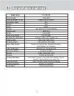
Summary of Contents for PS-M550WP

Page 1: ...EL PS M550WP CAUTION BEFORE SERVICING THE UNIT READ THE SAFETY PRECAUTIONS IN THIS MANUAL 삼 흥 정 판 P NO MFL31520606 February 2007 Printed in Korea AIR PURIFIER SERVICE MANUAL Website http biz lgservice com ...

Page 2: ...TION 8 PAGE 28 30 SECTION 9 PAGE 31 Safety instructions Logics Major Specifications of each Model Operations Functions Manual Main Components Disassemble Assemble and Repair Instruction Electric diagram Troubleshooting and inspection direction PCB Circuit Diagram Parts Layout Exploded View Svc Components inventory SECTION 10 PAGE 32 Replacement Parts List ...

Page 3: ...ove the round grounding prong from the plug Do not operate this or any electrical appliance when you smell gas Do not operate with wet hands or in a damp environment Do not disassemble or modify the air purifier or the power cord Do not use this or any appliance near flammable gases or liquids or other combustibles such as gasoline benzene thinner etc If you hear abnormal sounds or smell smoke imm...

Page 4: ...ords are a shock and fire hazard Do not place the power cord or Air Purifier near a heater radiator or other heat source This air purifier is not designed for use by young children Young children should be supervised to ensure that they do not play with or climb on the air purifier Do not use your Air Purifier to remove hair spray and insecticides from a room These chemicals not only clog the filt...

Page 5: ...ir purifier This unit is not intended to be used for the preservation of art objects or precision machinery Clean with a soft cloth and mild detergent Filter should be cleaned once a month Do not start or stop operation by plugging in or unplugging the power cord Always turn off and unplug the air purifier when it will not be used for extended periods of time This conserves energy and reduces the ...

Page 6: ...ay also emit VOCs It may stay remained in a closet or inside of furniture even after several years Filters Introduction 1 Pre filter One filter performs antibiotic treatment anti mold treatment and dust removal providing a purified air 2 Photo Catalyst Plasma Filter Photo Catalyst Plasma Filter removes microscopic motes odor yellow dusts and allergy causing substance through a 3 stage process plas...

Page 7: ...m 250mm 45m2 9 5kg White Easy design for convenient operation 35W Turbo Turbo 44dB Turbo 5 5CMM Generate 1million super negative ions Multi surface inhale system Three dimension filter system Pre filte r Anti allergic filter Washable HEPA filter Super Negative ion Sterilization Washable part Replacement part Ez remote controller Digital 2 Sensor dust smell Digital Wide LED display Dust Smell Purit...

Page 8: ... Mainframe Operation indicator and controller Off timer indicator Power On Off button Off timer button Function button Negative ion sterilization indicator Purity level indicator Level reflects how well the air purifier is cleaning the air Filter self checking indicator Check the filter when indicated by the light Operation indicator Fan speed indicator Operation Mode button Fan speed button Opera...

Page 9: ... from the air Eliminates food pet and other odors Removes alkaline acid and organic compound odors This filter uses jewelry grade platinum and should be disposed of properly when discarded Photo catalyst filter 10 11 Washable carbon Catalyst function Nano Platinum filter Allow the filter to dry completely before reinstalling If not completely dried it may cause the air purifier to malfunction or c...

Page 10: ...new batteries Press locking tab on the battery cover on the back of the remote and remove the cover Insert new batteries into the battery compartment being sure to note the proper polarity Reattach the battery cover making sure the locking tab clicks into place Press only one button on the remote at one time Press only one button on the remote at one time Pressing two or more buttons simultaneousl...

Page 11: ...ed mode User may manually adjust fan speed Automatic mode Air Purifier will automatically set the most appropriate Fan speed 1 Power ON OFF 1 MODE switches allows the user to select the various modes of operation including auto fan and sleep sandstorm and self timer modes 2 Automatic Mode When in AUTO mode the fan speed is automatically selected by the unit depending on pollution levels Even in th...

Page 12: ...omatically select the proper fan speed All other functions must be manually selected by the consumer 2 Yellow Sandstorm Mode Purifies indoor air even in extreme conditions such as a sandstorm Power ON OFF 1 Press MODE button until the SLEEP light illuminates on the unit When in the SLEEP mode the unit will automatically select low fan speed The consumer can increase the fan speed to the next highe...

Page 13: ...ically shut off Maximum reservation time is 9 hours Shut down automatically Automatically shut down 3 hours later 2 Off timer mode function Automatically shuts down after a preset amount of time Example shut down automatically after 3 hours Power ON OFF 1 Press the function button to choose expected function Press button each time switch according to negative ion negative ion sterilization functio...

Page 14: ...e Compensation Function Exterior Cleaning Method Dust sensor cleaning method Wipe the exterior of the air purifier with a soft cloth with warm water and mild detergent The dust sensor senses both small and large dust particles The sensor needs to be wiped clean to maintain high performance After cleaning the lens close the cover of the dust sensor in the reverse order Open the front panel to acces...

Page 15: ...e filter 5 HEPA and Deodorizing washable filter Soak in warm water for an hour Rinse NOTE The anti allergic filter should NOT be washed Washing this filter will reduce its efficiency Clean the washable HEPA filter and deodorization filter with warm water and rinse under running water Dry filter in a well ventilated room until completely dry Clean Pre Filter with vacuum or soft brush and mild deter...

Page 16: ...aintenance Remove plug from grounded outlet 1 Clean and protect the air purifier s mainframe Cover the air purifier when storing for an extended period of time 2 Clean with a soft cloth and mild detergent Exterior case may scratch easily ...

Page 17: ...r parts Please disassemble according to the instruction 2 Please do not disassemble unless it is absolutely necessary Do not disassemble any part that is not on the disassemble instruction Please unplug the power before disassemble Replacing a fan or a motor 1 Please remove 6 screws from the Case Back using a Screw Driver Take Handle Cover and Back Cover off 2 Unscrew bolts using a wrench Turn it ...

Page 18: ...Repair instruction 3 FAN is disassembled by holding and pulling fan 4 Please remove 3 screws from the Motor Cover using a Screw Driver 5 Remove the Motor Cover Take out the Motor Please be careful not to damage the Motor wire when removing the motor ...

Page 19: ...e Connector Bar 19 5 Major components Disassemble Assemble and Repair instruction PCB and Sensor Replacement 1 After pulling off the product front cover take out the Filter Assembly 3 Take out Front Panel Assembly Remove 2 screws from the Back Case and 4 screws from the Front Case using a screw driver ...

Page 20: ...ot to damage the Main PCB Wire when removing the Front Case Assembly 5 Remove 4 screws from the Main PCB using a screw driver You can also replace gas sensor dust sensor remote control sensor 6 Remove a screw from the Control PCB Case using a screw driver Remove 2 screws from the Power PCB using a screw driver ...

Page 21: ...a Connector Bar 1 After the Front Case Assembly separation remove screws from the Case Back and the Handle Cover 1 screw from the Handle Cover 3 screws from the Case Back Take off the Case Back 2 Remove 2 screws 1 each from left right from the Connector Bar using a screw driver ...

Page 22: ... 22 6 Electric diagram ...

Page 23: ...terminals 12V Are DC PCB ASM and Power PCB ASM CONECTOR correctly connected Is DC voltage on both C04 terminals of MAIN PCB ASM 5V Does the Reset alarm occur when the power is turned on Check LED Display soldering YES NO Make sure that power line is plugged in Check the fuse in Power PCB ASM FUSE Replace Power PCB ASM Check connections between Power PSB ASM and MAIN PCB ASM Replace MAIN PCB ASM Re...

Page 24: ...nnected Are MAIN PCB ASM and Dust Sensor Gas Sensor CONECTOR correctly connected Is the voltage of CN GAS PIN 1 3 CN DUST PIN 1 3 5V Replace MAIN PCB ASM Is voltage on both C01 terminals of MAIN PCB ASM 12V Replace MAIN PCB ASM YES YES YES YES NO NO NO NO Check CN ACDC connection Check CN GAS CN DUST connection Replace MAIN PCB ASM Replace Power PCB ASM ...

Page 25: ...Is the POWER PCB ASM CN MOTOR CONNECTOR plugged in properly Is the CN ACDC CONNECTOR of the POWER PCB ASM and MAIN PCB ASM connected properly Does the Operation shut off after 30 seconds of running Replace PCB ASM YES NO Check FILTER S W contact Replace POWER PCB ASM Check CN ACDC connection Check CN MOTOR connection Check after power off ...

Page 26: ...wer of POWER PCB ASM CN ACDC PIN2 8 Negative Ion and PIN2 9 Positive Ion AC220V Is the power of POWER PCB ASM CN ASEI PIN1 3 Negative Ion and PIN3 5 Positive Ion AC220V Are POWER PCB and NPI MODULE CONECTOR correctly connected Replace NPI MODULE YES NO YES NO YES NO YES NO YES NO Select Negative ion Positive ion Check CN ACDC connection Replace MAIN PCB ASM Replace POWER PCB ASM Check CN NSEI conn...

Page 27: ... 2 DC 5V Replace MAIN PCB ASM YES YES NO NO Check batteries of remote controller Plasma dust collector malfunction Is MICOM SWITCH connected properly Is the power of CN HVB CONNECTOR PIN 1 3 12V Is High voltage on both terminals of HVB ASSY present Replace Plasma Filter ASSEMBLY YES YES YES NO NO NO Replace MICOM SWITCH Replace MAIN PCB Replace HVB ASSY Check MAIN PCB ASM CN REC connection ...

Page 28: ... 28 PCB Circuit Diagram Parts Layouts DC PART Parts Layouts AC PART Parts Layouts 8 ...

Page 29: ... 29 8 PCB Circuit Diagram Parts Layouts DC PART Circuit Diagram ...

Page 30: ... 30 8 PCB Circuit Diagram Parts Layouts AC PART Circuit Diagram ...

Page 31: ...AUDA 5MDGAA 5MBNRA 5MCKHA 5EADAA 5FADAA 5EBRPP 1MCKSP 2MCKDU 2MCKDP 2MCKDE 7MDSAA 9AKBAA 5MBUAA 02 01 2MJPAA 1MCRPA 1MGCFA 5EAYAC 5MBNGA 7MDJMB 7MDJMA 1MEAGF 7MDJPA 7ADAPA 7MDJPB 7ADQHA 7ADQDA 7ADQAL 2EAYDC 2MBNFA 6EADTC 6EADTD 6EADWA 6EADTB 5MCKMC 6EADTA 6EADSA 1MGCSP 2EBDSD 2EBRPA 7MBNCF MODEL PS M550WP EV Exploded View ...

Page 32: ... 33 ...

Reviews: