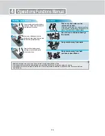


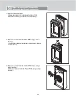


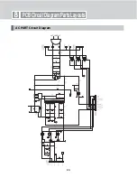

2. Separate Connector Bar from the Front Panel using a
screw driver (-).
(Please be careful not to damage the Connector Bar.)
-19-
5
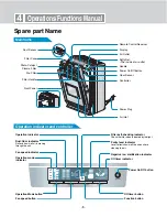
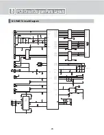
Major components Disassemble
Assemble and Repair instruction
PCB and Sensor Replacement
1. After pulling off the product front cover, take out the
Filter Assembly.
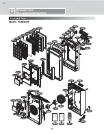
3. Take out Front Panel
Assembly.
Remove 2 screws from the
Back Case, and 4 screws from
the Front Case using a screw
).
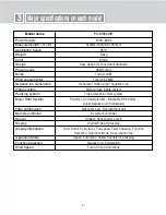
Summary of Contents for PS-M550WP
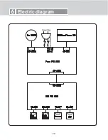
Page 22: ... 22 6 Electric diagram ...
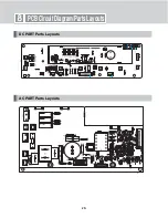
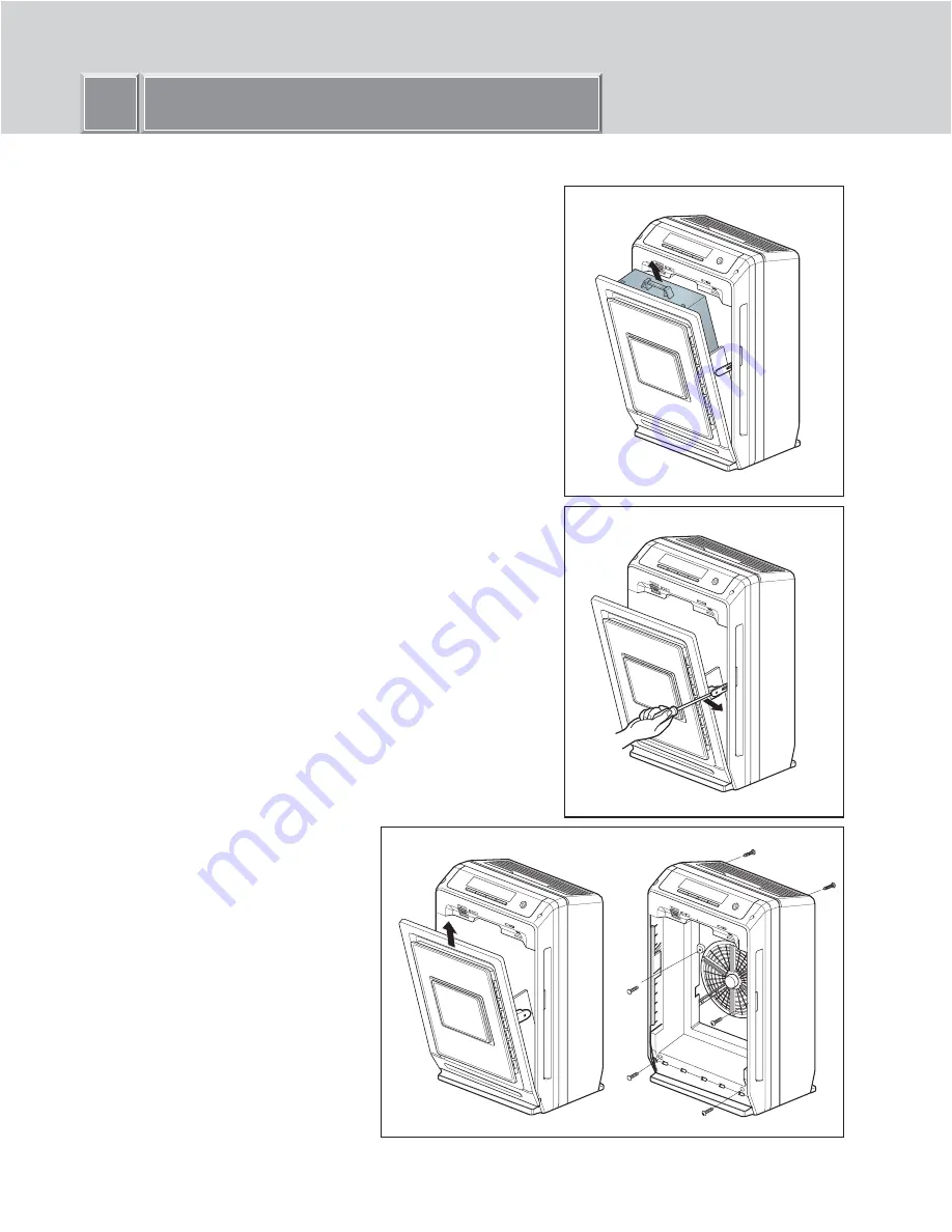
Page 28: ... 28 PCB Circuit Diagram Parts Layouts DC PART Parts Layouts AC PART Parts Layouts 8 ...
Page 29: ... 29 8 PCB Circuit Diagram Parts Layouts DC PART Circuit Diagram ...
Page 30: ... 30 8 PCB Circuit Diagram Parts Layouts AC PART Circuit Diagram ...
Page 32: ... 33 ...


